


□
16. Place the assembly upside down on the bench and put pressure along the leading edge to force the sheeting
into contact with the leading edge. Apply thin CA along the entire leading edge and let cure. Apply pressure
along the trailing edge and apply CA there as well. Trim the sheeting to within about 1⁄4” of the ply wing
tip, DO NOT glue the wing tip sheeting at this time.
□
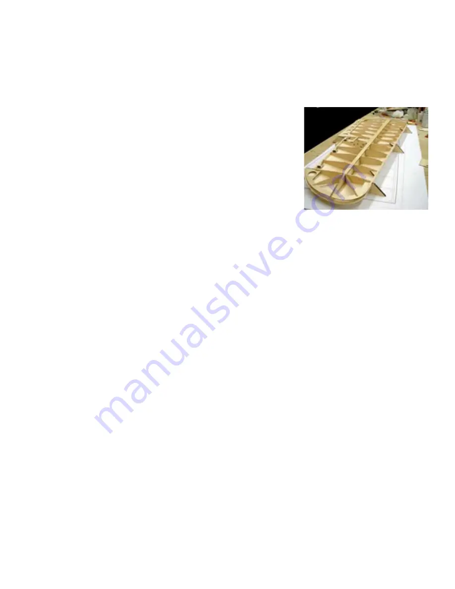
18. Plain all bottom leading and trailing edges to contour in preparation
for the bottom wing sheeting. A set of three jigs is supplied to support
the wing while installing the bottom sheeting. Glue some 2” pieces
of 1⁄4” x 1⁄2” balsa into the slots provided to support the jigs. Place
these 1⁄4” balsa jigs at W2, W7 and W12. Apply a liberal bead of glue
to the bottom of all ribs and the bottom spar flange except where
noted. Once again do not glue the last two inches of the spar flange
to accommodate adding the spar joiner. Also omit gluing around the
servo bay, this will make it easier to remove material for the servo
mount and will be glued with thin CA after the opening has been cut.
□
17. Install the two 3/32” ply servo mount rails. Use the 1/16” ply servo mount to align the screw holes for a
better fit. You can screw the rails to the cover and then glue assembly into position. Remove the screws
and cover when cured.
Wing assembly suspended on the rib jigs
at W2, W7 and W12. These jigs will sup-
port the wing assembly while the bottom
sheeting is being installed.
□
20. Assembly of the wing halves is a two-step process. First install two 1/4” x 1” dowels into the holes provided
in the 1⁄4” lite ply wing joiner rib. This rib will not only align the wing halves but also support the 1⁄4” wing
mounting dowel. It’s a good idea to use a piece of 1⁄4” carbon fiber rod for this component. Assemble the
wing halves with the ply wing joiner rib. Prop one wing tip up 4” at W12 for correct dihedral.
□
21. Use one of the 1/64” ply spar joiners as a template to mark and remove the wing sheeting from the top and
bottom spar flanges at the wing joint. Use slow setting Epoxy or finishing resin and lay in four of these
1/64” ply joiners with a liberal application of Epoxy between each one. Use plenty of pressure to keep the
ply joiner flush with the top of the balsa sheeting. When cured, turn the wing over and repeat the process
on the bottom spar flange.
□
22. Glue on the wing bolt plate.
□
23. Note that the aileron is laminated from three pieces. The bottom piece is 3/16” balsa, the center section is
assembled from 3/32” balsa and 3/32” ply and the top is 1/4” balsa. The ply aileron horn is glued into the
3/32” balsa center section first. These parts are provided with a 1/8” pinning hole at each end. Use a piece
of 1/8” music wire or the shank of a 1/8” drill bit in each hole to align the parts when laminating them
together. Note the stack order of the parts and be sure to make a left and a right.
□
19. After curing, use the same technique to glue the leading and trailing
edges with thin CA. Trim the tip as you did the top skin and then
starting at the center in line with the spar web, use thin CA to glue
both skins to the ply tip at the same time. This will help keep both sides even. Glue on the 1⁄4” leading edge’s
and plane and sand to shape.
□
24. A great tool for marking and shaping the ailerons is three 2” sections of 1/8” music wire rounded at each
end. Place these in the hinge holes in the aileron and then temporarily install onto the wing. These will hold
the aileron ridged while you mark the edges of the aileron assembly for shaping.
□
25. Glue the two 1/64” ply aileron cable opening liners about 1” behind the main spar and about 1” out from
the joiner rib. After gluing, remove the balsa from the center to allow access for your servo cables.
This concludes assembly of the wing.


