


43
SET THE
CONTR
OL THR
O
W
S
Use a Great Planes AccuThro
w
or a r
u
ler to
accur
ately measure and set the control thro
w of each
control surf
ace as indicated in the char
t that f
o
llo
ws
. If
y
o
ur r
adio does not ha
v
e
dual r
a
tes
, w
e
recommend
setting the thro
ws at the lo
w r
a
te setting.
NO
TE
: F
o
r the ailerons
, the thro
ws are measured at
the
widest par
t
(at the root end).
These are the recommended high and lo
w rate
contr
o
l surface thr
o
ws.
High Rate
Lo
w Rate
ELEV
A
T
OR:
1-1/4" up
1" up
1-1/4" do
wn
1" do
wn
[32mm]
[25mm]
R
U
DDER:
1-1/4" r
ight
3/4" r
ight
1-1/4" left
3/4" left
[32mm]
[19mm]
AILER
ONS:
5/8" up
3/8" up
5/8" do
wn
3/8" do
wn
[16mm]
[10mm]
*FLAPS:
1/2" [13mm]
1" [25mm]
(1/2
fl
ap)
(full
fl
ap)
*
1/4" [6mm] of do
wn ele
v
a
tor should be mix
ed in with full fl
ap defl
ection
to control
“pitch-up”
when fl
aps are e
xtended.
IMPOR
T
ANT
:
The
T
op Flite B-25J Mitchell ARF
has been
e
x
tensivel
y
fl
o
w
n and tested to arr
iv
e
at
the thro
ws at which it fl
ies best.
Flying y
our model
at these thro
ws will pro
v
ide y
ou with the g
reatest
chance f
o
r successful fi
rst
fl
ights
. If
, after y
ou ha
v
e
become accustomed to the w
a
y the B-25 fl
ies
,
y
o
u
w
o
uld lik
e to change the thro
ws to suit y
our taste
,
that is fi
ne
. Ho
w
e
v
e
r,
too m
uch control thro
w could
mak
e the model diffi
cult to control, so remember
,
“more is not alw
a
ys better
.”
IDENTIFY Y
OUR
MODEL
No matter if y
ou fl
y at an AMA sanctioned R/C club
site or if y
ou fl
y some
where on y
our o
wn, y
ou should
alw
a
ys ha
v
e
y
o
ur name
, address
, telephone n
umber
and AMA n
umber on or inside y
our model.
It is
required
at all AMA R/C club fl
ying sites and AMA sanctioned
fl
ying e
v
ents
. Fill out the identifi
cation tag on the decal
sheet and place it on or inside y
our model.
CHARGE THE
B
A
TTERIES
F
o
llo
w
the batter
y
charging instr
uctions that came with
y
o
ur r
adio control system to charge the batter
ies
. Y
o
u
should alw
a
ys charge y
our tr
ansmitter and receiv
e
r
batter
ies the night bef
ore y
ou go fl
ying, and at other
times as recommended b
y
the r
adio man
uf
acturer
.
CA
UTION:
Unless the instr
uctions that came with
y
o
ur r
adio system state diff
erently
, the
initial
charge
on
ne
w
tr
ansmitter and receiv
e
r batter
ies should
be done f
o
r 15 hours
using the slo
w
-c
har
g
e
r that
came with the radio system
.
This will "condition"
the batter
ies so that the ne
xt charge ma
y be done
using the f
ast-charger of y
our choice
. If the initial
charge is done with a f
ast-charger the batter
ies
ma
y not reach their full capacity and y
ou ma
y be
fl
ying with batter
ies that are only par
tially charged.
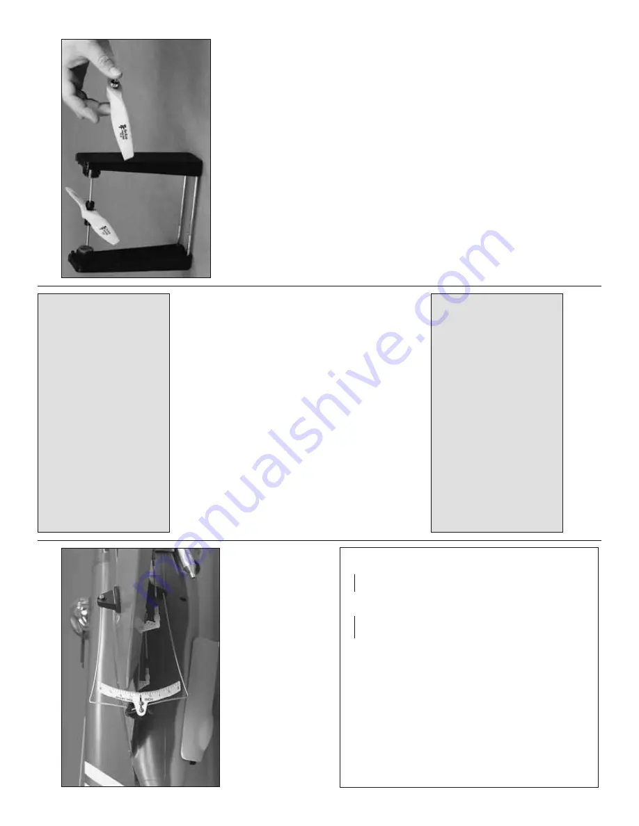
B
A
LANCE PR
OPELLERS
Carefully balance y
our propeller and spare propellers
bef
ore y
o
u fl
y
. An unbalanced prop can be the single
most signifi
cant cause of vibr
ation that can damage
y
o
ur model.
Not only will engine mounting scre
w
s
and bolts loosen, possib
ly with disastrous eff
ect, b
u
t
vibr
ation ma
y also damage y
o
ur r
adio receiv
e
r and
batter
y.
Vibr
a
tion can also cause y
our fuel to f
oam,
which will, in tur
n
, cause y
our engine to r
un hot or quit.
W
e
use a
T
o
p Flite Precision Magnetic Prop Balancer
(T
OPQ5700) in the w
o
rkshop and k
eep a Great
Planes Finger
tip Prop Balancer (GPMQ5000) in our
fl ight
bo
x.
GR
OUND CHECK
If the engines are ne
w
, f
o
llo
w the engine
man
ufacturer’
s
instructions to break-in the
engines.
After break-in, confi
r
m
that the engines idle
reliab
ly
, tr
ansition smoothly and r
apidly to full po
w
e
r
and maintain full po
w
e
r—indefi
nitely
. After y
ou r
un
the engines on the model, inspect the model closely
to mak
e sure all scre
ws remained tight, the hinges
are secure
, the props are secure and all pushrods
and connectors are secure
.


