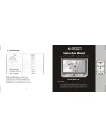
COMPONENTS AND CONTROLS
SETUP
7
Fuel cap
Power switch
(79991 None)
Fuel valve
Frame
Choke
Air filter
Starter handle
Low oil indicator
Voltmeter
Ground terminals
230VAC receptacle
Circuit breaker
Overload reset button
12VDC receptacle
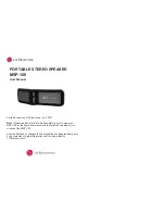
The following are descriptions of the controls on the power panel. Your Generator has sockets
to power your products with circuit breakers to protect the voltage flow.
1. I O START Engine Switch: Used to start and stop the Engine.
2. AC Receptacles: The Generator contains several AC Receptacles to power tools and equipment.
3.ON OFF Circuit Breakers: The circuit breaker protects the Generator from overloading. The
rating of the breaker and the load it protects are marked near the breaker. Should any of the
Circuit Breakers trip, the Generator will stop the electricity output. If this happens, unplug all
loads from the Generator. Allow the Generator to cool down. Then, press the tripped Circuit
Breaker, restart the Engine, and re-attach loads.
4. Grounding Terminal: Prior to each use, set up the ground wire (not included) connection
to the Grounding Terminal to properly ground the Generator. Refer to Grounding on page 8
for instructions on grounding the Generator
5. Grounding Terminal: Prior to each use, set up the ground wire (not included) connection to the Grounding
Terminal to properly ground the Generator.
Warning:
Connect tools and equipment only to the Receptacle (230volt) that is compatible with the
electrical characteristics and rated capacities of the tools and equipment being used.
Foldable handle
(79991 None)