


7.3
Physical Object Setup
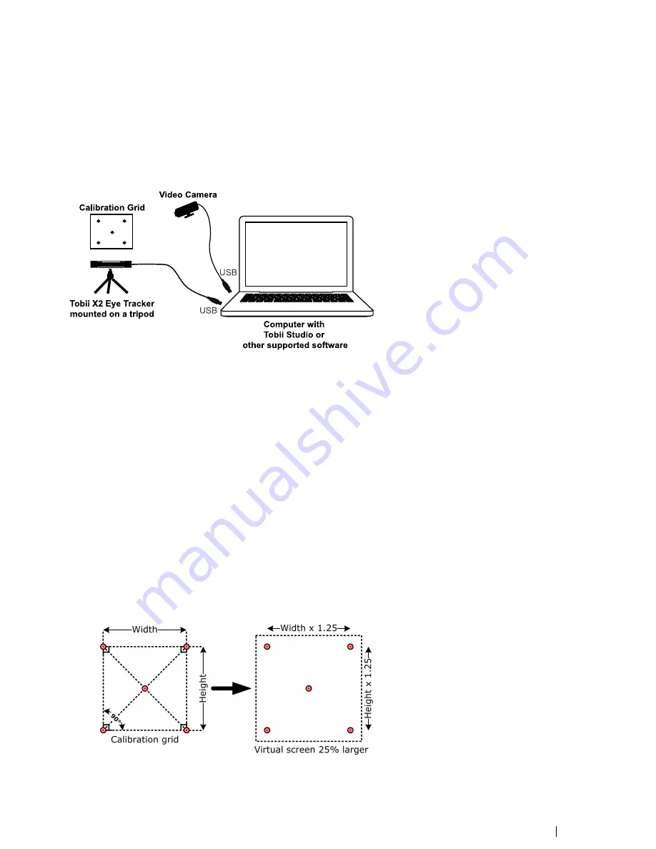
Real objects, such as magazines or mobile devices, can be used as stimuli in a scene camera setup where a video camera is film-
ing the object during the recording. In this setup, the calibration points cannot be displayed on a screen during the calibration,
thus a separate calibration grid must be used. The grid can be drawn on a paper and include five or nine points. The object you
intend to track should fit within an area which is 25% larger than the actual calibration grid. Always make sure that the eye tracker
is able to track the participant
’
s eyes over the entire calibration grid. During the calibration procedure, the participant is asked to
look at the corresponding points in the grid.
Vid e o Ca m e ra
Co m p u te r with
To b ii S tu d io o r
other supported software
Ca lib ra tio n Grid
To b ii X2 Eye Tra c ke r
mou nted on a t ripod
U
S B
US B
To configure this setup:
1.
Mount the eye tracker on a tripod, using the supplied desk stand as instructed in
4.2.2 Mounting the Tobii X2 Eye Tracker
Using a Desk Stand/Tripod, page 8.
2.
Connect the eye tracker to the computer via USB.
3.
Connect the scene camera to the computer.
4.
Position the eye tracker, taking into consideration the guidelines in
6 Positioning, page 19. Always make sure the eye
tracker is able to track the eyes over the entire object by using the correct distance to the screen and the correct tilt angle
of the eye tracker.
5.
If you don
’
t already have one, create a calibration grid. The calibration grid must have the same shape as the calibration
pattern used in Tobii Studio and include either five or nine points. The calibration points can be drawn on a paper, marked
on a calibration board, or marked on objects in the scene. Make sure that the corners of the calibration grid are exactly
90 degrees and that the center point is exactly in the middle of the grid. It is also good to include the 25% larger Active
Display Area around the grid to make it easier to measure the parameters required in the X Configuration Tool (see the
next step).
6.
Run the X Configuration Tool in order to configure the eye tracker for your particular setup. Please read
5 The X Configu-
ration Tool, page 15. How to calculate the 25% larger Active Display Area, which needs to be added in the X Configura-
tion Tool, is described below:
•
Active Display Area Height = 1.25 × Calibration grid height.
•
Active Display Area Width = 1.25 × Calibration grid width.
Tobii X2-30 Eye TrackerUser
’
s manual v.1.0.3 - en-US
7 Typical Setups
23


