Toa WT-D5800 Software Instruction Manual Download Page 5

5

2.2. Installation of USB Driver

The USB driver is required to be installed in order to connect the WT-D5800 with the PC. There are 2 methods 

to install the driver.

Tips

•  The following shows the display on Windows 10. A similar display will be shown on Windows 8.1 and Windows 7.

•  The USB driver can occasionally be re-installed when a different USB port is used to connect to the receiver 

from the one used for the initial driver installation. When this occurs, please wait till the Completion dialog is 

displayed.

2.2.1. Windows update

While the PC is connected to the Internet, connecting WT-D5800 with the PC will automatically take you to the 

Windows Update Website, and the USB driver required for WT-D5800 will be automatically installed on the PC. 

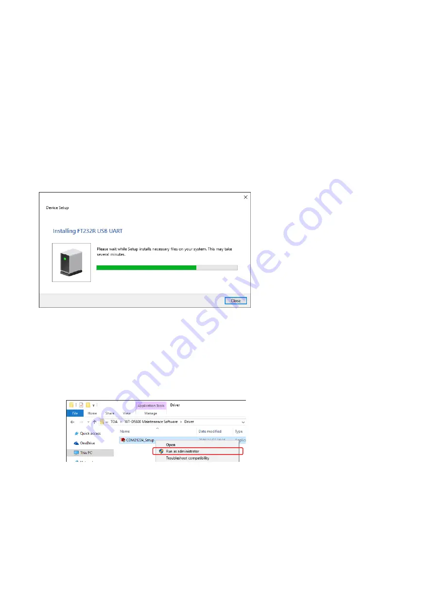
The following screen will be displayed during the driver installation.

2.2.2. Installation of downloaded data

The downloaded WT-D5800 Maintenance Software (Se

p. 4

) folder contains the USB driver data.

Select the data to install the driver.

Step 1. Open the driver folder in the installation folder.

Step 2. Right click on an execution file called “xxxx_Setup.exe” and select “Run as administrator.”

2

Step 3. Install the driver by following the instructions on the screen.

Note 

After  running  the  execution  file,  the  WT-D5800  must  be  physically  connected  to  the  PC  to  complete  the 

installation.

Summary of Contents for WT-D5800

Page 1: ...tal Wireless Microphone System WT D5800 Maintenance Software Thank you for purchasing TOA s digital wireless microphone system Please carefully follow the instructions in this manual to ensure long tr...

Page 2: ...Scan Screen 11 6 2 How to Use Channel Scan Function 12 7 SYSTEM STATUS DISPLAY 14 7 1 Receiver Display 14 7 2 When There is No Sound or the Sound is Disrupted 15 7 3 Checking the Signal Status by Reco...

Page 3: ...r or greater Free hard disk space 200 MB or greater USB USB 2 0 Software requirements OS Windows 7 SP1 32 64 bit Windows 8 1 32 64 bit Windows 10 32 64 bit Note Windows is the registered trademark of...

Page 4: ...configuration is shown below The Log Files created by this software will be stored in the data folder shown below C ProgramData TOA WT D5800 log Installation folder WT D5800_software exe Execution pro...

Page 5: ...Internet connecting WT D5800 with the PC will automatically take you to the Windows Update Website and the USB driver required for WT D5800 will be automatically installed on the PC The following scr...

Page 6: ...on the Windows icon on the lower left corner of the screen to switch it to the Start screen 2 Click on the search icon on the upper right corner of the screen to pull up the search window 3 Enter dev...

Page 7: ...t using the USB hub Use USB 2 0 A connector pair B connector type Use USB hubs that fit the shape of the connectors Example for connecting 16 receivers Connect the PC with each WT D5800 Digital Wirele...

Page 8: ...the USB cable and start connecting Once connecting starts the button will be switched to the Disconnect button Clicking the Disconnect button will stop the connection to the receiver Once connecting s...

Page 9: ...See p 18 Convert to Text Opens the screen where the log files are converted into text See p 19 Open Log Folder Opens the data folder in Explorer See p 4 Walk Test Log Records the reception status log...

Page 10: ...e PC 2 Walk Test button Used to conduct the Walk Test See p 20 3 Channel Scan button Used to check unused channels See p 11 CHANNEL SCAN 4 Spectrum Scan button Used to check interference See p 24 COND...

Page 11: ...1 Channel Scan Screen 1 No Displays the receiver s number 2 Scan result display Shows the channels in the horizontal axis and the reception level on the vertical axis as a graph 3 Marker Clicking or...

Page 12: ...re shown Step 1 Turn off all the microphone switches Step 2 Select a receiver that is connected from the list on the main screen and click on the Channel Scan button Main Screen 2 Displays the Channel...

Page 13: ...tion levels can be considered available Step 7 Click on the Stop Scan button Channel Scan will stop Step 8 Make a channel plan according to the results The channels with higher reception are considere...

Page 14: ...etting 6 Code Displays the assigned Code number when the Encryption setting is OFF 7 FBS Displays the ON OFF status of the FBS setting 8 EQ Displays the status of the EQ setting 9 Status Displays the...

Page 15: ...rrect setting See Antenna instruction manual The receiver s reception indicators light red The Encryption setting or the code setting does not match even though the banks and channels of the microphon...

Page 16: ...e signal that the receiver is receiving is not strong enough This is not shown by default Encryption setting ON OFF status ID setting and code setting 5 Data Error bluish green Shows the data error wh...

Page 17: ...right corner on the main screen during recording Notes Do not turn off or disconnect the receiver while the Background Log is being recorded This will prevent the Background log from being stored Rest...

Page 18: ...he file name Step 1 Select Log Background Log View Log Data from the menu The Background Log screen will be displayed Step 2 Click the Open Log button Step 3 Select a Log File The selected log data wi...

Page 19: ...older p 4 See p 4 for the file name Step 1 Select Log Background Log Convert to Text from the menu Opens the screen where the log files are converted into text Step 2 Select a log file and click on th...

Page 20: ...is receiving signals from the microphone and can output sound Sync Error can occur when the settings of the receiver and the microphone do not match or the signal that the receiver is receiving is no...

Page 21: ...lts of the Walk Test in a file The log file will be stored in the data folder p 4 See p 4 for the file name 14 Open Log button Used to open the screen of the past Walk Test results Walk Test Log scree...

Page 22: ...will be forced to end Step 8 Click on the Save Log button when the result of the Walk Test needs to be saved as log data The log file will be stored in the data folder p 4 See p 4 for the file name S...

Page 23: ...y the log data to be displayed The log file will be stored in the data folder p 4 See p 4 for the file name The Walk Test Log will be displayed File name Except that the file name is displayed the con...

Page 24: ...uency and reception level on the Marker display 11 4 Scroll button Scrolls the graph in the horizontal direction 5 Start Scan button Starts scanning Scanning will continue until the Scan Stop button i...

Page 25: ...result Spectrum Scan Log screen Spectrum Scan log files will be displayed for selection by clicking this button 15 Change View button Clicking the Change View button will change the horizontal axis t...

Page 26: ...the Stop Scan button Stops the Spectrum Scan Note After 7 days 168 hours the recording will be forced to end Step 7 Click on the Save Log button when the result of the Spectrum Scan needs to be saved...

Page 27: ...file will be stored in the data folder p 4 See p 4 for the file name Displays the Spectrum Scan Log screen File name 3 3 Tip Clicking the Change View button will change the horizontal axis to show ti...

Page 28: ...trol acoustic feedback dynamically When the setting is OFF the parameters for the FBS filter will not be set automatically and the feedback will not be controlled dynamically When the function is turn...

Page 29: ...01703 11 STOPPING CONNECTION WITH RECEIVERS Clicking the Disconnect button on the main screen will stop the connection to the receivers When the connection is stopped the information on the receiver d...

Reviews: