14
3. Generate Code
When performing any function operation, press this button and the corresponding command will be displayed below the software.
4. Help
Click the Help , a pop-up window will display the information of the current software.
Page 1: ...TING INSTRUCTIONS DIGITAL MATRIX MIXER SYSTEM M 8080D SERIES Thank you for purchasing TOA s Digital Matrix Mixer System Please carefully follow the instructions in this manual to ensure long trouble free use of your equipment ...
Page 2: ...IO 8 5 M 800RCT 8 6 M 804EX 9 APPLICATION EXAMPLES 10 APPENDIX 11 SPECIFICATIONS 6 6 6 7 7 9 10 12 15 15 17 18 19 20 22 23 25 28 28 31 33 35 36 40 41 44 45 1 IMPORTANT SAFETY INSTRUCTIONS 3 11 2 REMOTE MICROPHONE M 800RM 11 3 REMOTE AUDIO CONTROL PANEL M 800RC 11 4 REMOTE AUDIO CONTROL PANEL WITH AUDIO OUT M 802RC 11 5 REMOTE AUDIO INPUT OUTPUT PANEL M 822IO 11 6 REMOTE AUDIO CONTROL PANEL WITH TO...
Page 3: ...erver ces instructions pour référence ultérieure Respecter tous les avertissements Suivre toutes les instructions Ne pas utiliser cet appareil à proximité d eau Nettoyer uniquement à l aide d un chiffon sec Ne pas obstruer les orifices de ventilation Installer conformément aux instructions du fabricant Ne pas installer à proximité de sources de chaleur telles que des radiateurs des registres therm...
Page 4: ...s into the unit If the unit falls or the unit case breaks If the power supply cord is damaged exposure of the core disconnection etc If it is malfunctioning no tone sounds To prevent a fire or electric shock never open nor remove the unit case as there are high voltage components inside the unit Refer all servicing to your nearest TOA dealer Do not place cups bowls or other containers of liquid or...
Page 5: ...this may cause it to fall or break which may result in personal injury and or property damage In addition the object itself may fall off and cause injury and or damage Make sure that the volume control is set to minimum position before power is switched on Loud noise produced at high volume when power is switched on can impair hearing Do not operate the unit for an extended period of time with the...
Page 6: ...alogue OUT on rear panel ports of M 8080D Optional 4 digital IN 4 digital OUT via remote devices analog I O Max System I O 12 x 12 Remote devices Audio IN Audio OUT Optional remote devices with Audio I O Consumption on Audio I O from devices in regards to additional available 4 digital IN 4 digital OUT per M 8080D Note Only 2x devices of the above mentioned controllers can be connected physically ...
Page 7: ...85 for panel control and AES3 for digital audio transport TCP IP for LAN control Cable connections for Remote Controllers RD ports Use shielded CAT 5e or better cable to connect the remote controllers to the RD ports The maximum transmission distance is 100 meters If in wall mounted controllers can be connected to the ground except the Paging Station the distance can be increased up to 150 meters ...
Page 8: ... information software update and status information from M 8080D to remote device Note Configuration information of remote device such LED illuminate status microphone sensitivity channel name etc is stored in M 8080D not in the remote devices This makes easy to swap for a new remote device without losing the configured information The orange and blue pairs carry two channels each of balanced diff...
Page 9: ...nately e DSP connection indicator In case of problem DSP will be displayed a b c d e 2 ANALOG Analog input indicators The Green LED indicates presence of signal the Red LED indicates signal clipping of the corresponding input 3 RD RD digital input indicators The Green LED indicates presence of signal the Red LED indicates signal clipping of the corresponding input 4 ANALOG Analog output indicators...
Page 10: ...ernet connection 10 100M adaptive with DHCP function The plug includes two LEDs a green one indicating the good connection to the network and a yellow one indicating the good data transmission If the yellow LED turns Off there is a transmission problem If On with Green LED Off the device has detected the network but there is no connection If the Green LED is on the network connection is correct 3 ...
Page 11: ...s 11 and 12 8 RELAY Dry contacts where ON OFF status can be individually controlled in the System menu Please refer to page 23 They are generally used as switches for third party electrical equipment Attention withstand voltage 24V DC control current Under 500mA 9 RS232 This interface is used to remotely control M 8080D parameters such as a Preset change or a modification of the gain for one chann...
Page 12: ...duction Open Load local preset files Save As Save current preset to local Press this button to save all current presets except the preset list data Offline Load Only for TOA technicians to offline analyze whether the user preset files are correct Config Device ID Customize device ID The ID shall be always 0100 Offline Save Note M 800RM only cannot save offline Only for TOA technicians after offlin...
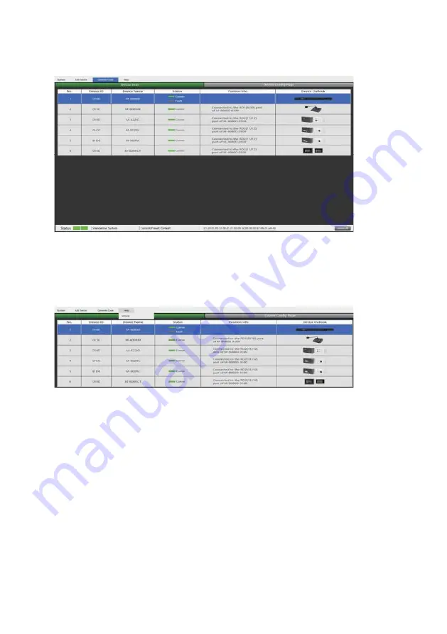
Page 13: ...h to scan the devices After adding to the device list enter the following page Refresh Refresh the current online status of the device Select All Select all current online devices Add Add the selected device to the device information list Selecting the device to add to the information list and enter the following page Device Info can clearly and intuitively see Device ID Device Name Status Positio...
Page 14: ...de When performing any function operation press this button and the corresponding command will be displayed below the software 4 Help Click the Help a pop up window will display the information of the current software ...
Page 15: ... reaction time when the signal is above the specified threshold from 10 to 150 ms The attack time is how long it takes the gate to fully open once this threshold has been reached Release reaction time of the Expander when the signal passes below the specified threshold from 10ms to 1000 ms Bypass Press this button the function of this area is invalid Default Restore this area to default settings 2...
Page 16: ...en the signal exceeds the Threshold it is compressed in a ratio greater than 1 Below the Threshold input and output signals remain the same By adjusting the ratio to its maximum value the compressor is transformed into a limiter a Threshold Threshold from which the signal is compressed from 30dB to 20dB b Ratio Compression ratio For instance a 4 1 ratio means that the input level is 4dB above the ...
Page 17: ...2 5 Gain to 2 5dB EQ3 type to 1 45kHz The Q value is unchanged The gain is attenuated to 2 5dB The EQ4 type is adjusted to 406 1Hz The Q value gain is unchanged and the EQ5 type is adjusted to 8 38KHz The Q value does not change and the gain reaches 4dB 7 2 MATRIX This part of the software is used to route inputs through a graphical representation as a matrix By clicking on the gray boxes several ...
Page 18: ...lly turned off The purpose is to avoid no broadcast but also has output Function Example Assign input 1 to output 1 when the sound is adjusted to 29dB press OK The sound of channel 1 will be adjusted to 29dB 7 3 OUTPUT DSP CHANNEL Same menu as the Input DSP Channel without the Expander Gate section The parametric EQ features 8 bands here instead of 5 bands for the inputs Please refer to the introd...
Page 19: ... main applications are automatic speech for conference or priority messages E g Use the host microphone signal to control the background music volume The host automatically reduces the background music volume when speaking After the speech the volume of BGM music is automatically restored 1 Ducker Input Priority Setting Each input corresponds to each output This area is used to set the priority of...
Page 20: ...t processed and skips to the next processing module Function Example The current setting sets channel 1 to level 1 channel 2 to level 2 and channel 3 to level 3 At the same time the Threshold depth and Active time are set at the bottom of the page The audio source will be output according to the previously set priority and other parameters 7 5 FBC FEEDBACK COMPRESSION 20 1 2 8 7 3 5 4 6 9 ...
Page 21: ... green FBC Setting 3 FBC Mode Speech Music is suitable for meetings and music occasions howling and clearing are automatically captured 4 Filter Release Fast Mid Low Click here to determine the speed of dynamic filter elimination Fast Mid Slow FBC Setup 5 Static Filters Setup The default is a dynamic filter the indicator is green Click Static Filter Setup to switch to static filter the indicator l...
Page 22: ...ls to the required level and turn on the microphone Manually gain FBC until howling occurs in this mode the FBC module will automatically use a static filter Static filter indicator is red 7 6 AUTO MIXER The Auto mixer automatically controls the gains of multiple microphones in real time dramatically reducing feedback noise and comb filtering from adjacent microphones It maintains a consistent sys...
Page 23: ...fader to set the time value Function Example Add the local input CH 1 and CH2 open setting to the automatic mixing function Input the audio source from two channels Click the ON button of Active Time and push the fader to set the start mixing time of the CH 1 and CH2 signal For example drag the fader to 900ms the sound source of channel 1 will be at 900ms and the mixing function is added 7 7 SAVE ...
Page 24: ...en when reloaded a If Device is selected Load First to select a preset click OK to load wait a few seconds until finished Save Select a preset in the preset list then customize the name Click Save button and the modification will be successful Delete Select a preset and click Delete the preset will be deleted b When Local PC is selected Load Select Local PC and click Load indicating that the prese...
Page 25: ...ndow 3 Click Submit button to save the preset Note The preset list are saved separately and are not included in the system saving Function Example 2 Select the input channel Input1 to copy to CH03 Click the COPY button the parameters of input channel 1 will be copied to CH03 7 8 SYSTEM 25 1 8 9 6 10 7 2 4 3 5 ...
Page 26: ...me of the selected I O Note The open voltage of GPI is 1 5V and the open resistance is 200Ω It is only used for relay or switch control 9 Priority Input Level Select input 1 8 for priority control 10 Output gain for priority It used to control the output gain of the priority channel Wire drawing GPI 2 short 1 Put the cable insert to the GPI 2 port in the back plate 2 The other end connects the gre...
Page 27: ...le 2 1 According to the method described earlier insert one end of the network cable into the GPI 1 port on the rear panel of the machine and the other end is short circuited 2 The GPI 1 port on the PC software lights up to indicate that this function is enabled 3 According to the set input priority and the selected input 1 At this point only the input 1 input signal has output ...
Page 28: ...atus indicators The green LED indicates the presence of signal when the microphone is ON The red LED indicates the limit of clipping c Communication status indicators When the communication with the M 8080D is correct the green LED blinks In case of problem the BUSY red LED lights up d Volume control and all zone selector It controls the volume of the microphone for each selected zones By pushing ...
Page 29: ... display a removable storage disk 3 Drag the chimes you want into the Removable disk to complete the USB audio import Caution The maximum storage space of the device is 1MB i RD port Connection to the M 8080D The maximum CAT 5e cable length is 100 meters Attention 1 M 800RM M 822IO M 802RC with audio transmission can only be connected to the RD port of the M 8080D or the RD EXP port 1 of M 804EX 2...
Page 30: ...Chime playing time The interval is 0 1S 12S 7 Master Volume Audio master volume adjustment The volume level is 0 32dB 8 Chime Volume Control the playback volume of audio files the volume level is 0 32dB 9 Mic Volume Microphone volume adjustment The volume level is 0 32dB 10 Priority Priority setting The priority level is 1 16 Higher level higher number has higher priority 11 Load from Device Load ...
Page 31: ...in 100 meters in total from M 8080D RD port to last controller 100 meters d RD EXP Daisy connection for additional remote controller 4 controllers max Attention 1 M 800RM M 822IO M 802RC with audio transmission can only be connected to the RD port of the M 8080D or the RD EXP port 1 of M 804EX 2 M 800RC M 800RCT with control function can link each other Wall installation instructions 1 First unscr...
Page 32: ...e set You must first lock and then unlock with 0000 to set a new lock password 4 Device Name Setting Click the box to modify it and click Save To Device to save successfully 5 Load From Device Load presets from device 6 Save To Device Save the current parameters to the device 7 Screen Saver After checking this box the machine will sleep after one minute of inactivity 8 Default Restore the default ...
Page 33: ... RD IN Connection to M 8080D or M 804EX The maximum CAT 5e cable length is 100 meters Attention 1 M 800RM M 822IO M 802RC with audio transmission can only be connected to the RD port of the M 8080D or the RD EXP port 1 of M 804EX 2 M 800RC M 800RCT with control function can link each other d Analog OUT 2 channel analog line Outputs assigned to RD port 9 10 or 11 12 of M 8080D Wall installation ins...
Page 34: ...g you must first lock and then unlock with 0000 to set a new lock password 4 Device Name Setting Click to modify the device name after modification click Save To Device to save 5 Load From Device Load presets from device 6 Save to Device Save preset parameters to the device 7 Screen Saver After checking this box the machine will sleep after one minute of inactivity 8 Default Initialization paramet...
Page 35: ...s the A channel input c Microphone volume Button to adjust the MIC input level d Phantom power 48V switchable phantom power for electret MIC e Signal indicators for the Inputs Chanel A MIC and B input signal status indicators for signal presence and clip f Signal indicators for the Outputs RD port 9 10 or 11 12 output input signal status indicators g RD IN Connection to M 8080D or M 804EX The maxi...
Page 36: ...e into the RD IN port Connect the analog output cable and snap the device to the back plate Tighten the bottom with screws 4 Cover the decorative panel The M 800RCT is a wall mount 4 3 touch LC Display volume controller The volume control can be assigned to any output of the M 8080D It can also route any input to any output like in Matrix menu of the Editor Software a RD IN Connection to M 8080D o...
Page 37: ...nto the RD IN port and snap the device to the rear panel Tighten the bottom with screws The installation diagram is as follows The device can set up four different sub menu pages like Input Output Preset and System In the Input section volume and mute can be adjusted and visually monitored 1 CH 01 CH 12 Select input channel 01 12 Adjustable input volume 2 Fader Slide the lever to adjust the input ...
Page 38: ...M 8080D 1 Preset List All the presets on the main unit are displayed here 2 UP Page up 3 DOWN Page down 4 LOAD Select a preset and click LOAD to load as current preset 5 Flashing here means normal communication 6 MENU Click this function to return to the menu bar 2 3 4 5 6 1 2 3 4 5 1 The System section displays the firmware version address and device name It also switches the language option 1 Th...
Page 39: ...he input interface cannot be entered Output page After unchecking this box the display interface is disabled and the output interface cannot be entered Preset page After unchecking this box the display interface is disabled and you cannot enter the preset list interface 4 Device Name Setting Click to customize the device name and then click Save To Device to save successfully 5 Lock System The use...
Page 40: ... 802RC M 822IO M 800RM control and audio transport data remote devices d RD connection with Note Each Each RD EXP port can support up to 4pcs The maximum CAT 5e cable length for daisy chain 100 meters in total from M 8080D RD port to last controller M 800RC M 800RCT M 8080D RD port can support up to 1pc M 804EX cannot connect another M 804EX through the RD EXP port M 8080D 7 Save to Device Save th...
Page 41: ...o M 8080D to broadcast Music Messages Advertisement The computer can be used to edit the M 8080D as well M 800RC M 822IO HX 7B W F 2000BT WT C C Music Player M 800RCT GYM M 800RM M 8080D M 804EX DA 250FH Aerobics Room Treadmill Room Lobby BS 1034W Flexible sound control Volume and presets can be controlled from the lobby by touch panel remote controller M 800RCT In Aerobics Rooms instructors can p...
Page 42: ...lled from the reception using M 800RCT Touch Panel Controller MALL M 800RM M 8080D DA 500FH DA 500FH EV 20R Control up to 12 independent zones with a single M 8080D M 8080D feeds 2 x 4 analog inputs of amplifiers Each amplifier offers 4 individual lines of high impedance speakers to broadcast BGM program live paging and pre recorded announcement in separate zones For more zones 2 x additional OUT ...
Page 43: ...ESTAURANT BAR M 800RM M 8080D DA 250FH Easy and quick volume control for operators 4 analog outputs of M 8080D are used for 4 separate zones with volume controlled from the lobby Two additional line out come from the M 802RC remote controller using digital connection from the M 8080D It feeds the bar area where M 802RC remote can be replaced by M 822IO In Out interface for DJ show or Karaoke sessi...
Page 44: ...Receive Input Status 6 0x01 0x20 0x03 0x00 0x10 0x00 0x06 0x01 High Byte of ID address 0x00 Low Byte of ID address 0xA5 0xE8 0x00 0x05 Channel 1 12 0x01 0x0C 1 Byte Volume 0x00 0xBE 1 Byte 0x40 Output Gain 7 0x01 0x20 0x03 0x00 0x10 0x00 0x06 0x01 High Byte of ID address 0x00 Low Byte of ID address 0xA5 0xE8 0x00 0x06 Channel 1 12 0x01 0x0C 1 Byte Phase 0x00 Normal 0x01 Invert 1Byte 0x40 Output Ph...
Page 45: ...s 0xA5 0xE8 0x00 0x0D Channel 1 12 0x01 0x0C 1 Byte Invalid 0x00 1Byte 0x40 Output Gain Up Step 1dB 17 0x01 0x20 0x03 0x00 0x10 0x00 0x06 0x01 High Byte of ID address 0x00 Low Byte of ID address 0xA5 0xE8 0x00 0x0E Channel 1 12 0x01 0x0C 1 Byte Invalid 0x00 1Byte 0x40 output Gain Down Step 1dB 18 0x01 0x20 0x03 0x00 0x10 0x00 0x06 0x01 High Byte of ID address 0x00 Low Byte of ID address 0xA5 0xE8 ...
Page 46: ...ttack 10 150 ms 5 0 1 5 5 1 6 0 1 6 5 1 7 0 1 7 5 1 8 0 1 8 5 1 9 0 1 9 5 1 10 0 1 gate Equalizer Filter 5 band EQ LPF and HPF for IN and 8 band EQ LPF and HPF for OUT Parametric Equalizer 19 7 20 160 Hz range 18 dB Q 0 4 128 Type peak low high Filter High pass Filter 19 7 20 160 Hz Type Butterworth 6 12 18 24 30 36 42 48 dB Bessel 6 12 18 24 30 36 42 48 dB Linkwitz 12 24 36 48 dB Low pass Filter ...
Page 47: ...V MP3 files for chimes sound Microphone volume control and all zone selector Volume Control Can address 1 to 64 different zones Zone selector LC display Display Displays device information ID volume zone selector Power Source 24V DC Powered by M 8080D or M 804EX Displays device information ID Volume communication status Operating Temperature 0 C to 40 C 32 F to 104 F Operating Humidity 90 RH or le...
Page 48: ...uivalent Panel Polycarbonate ABS black Plastic anchor 4 Power Source 24V DC Powered by M 8080D or M 804EX Line input A B 0 dBV 5 1 kΩ unbalanced RCA pin jack Over 79 dB A weighted S N Ratio Over 105 dB A weighted Operating Temperature 0 C to 40 C 32 F to 104 F Operating Humidity 90 RH or less no condensation Finish Dimensions 147 W x 86 H x 52 D mm 5 79 x 3 39 x 2 05 Weight 0 3 kg Accessory Freque...
Page 49: ...control data connect to M 800RC or M 800RCT RJ45 Connector Case Surface treated steel plate black paint maximum cable length 100 meters in total from M 8080D RD port to last controller maximum cable length 100 meters in total from M 8080D RD port to last controller Power Source 24V DC Powered by M 8080D or M 804EX Displays device information ID Volume preset communication status system etc Operati...
Page 50: ...armful interference to radio communications However there is no guarantee that interference will not occur in a particular installation If this equipment does cause harmful interference to radio or television reception which can be determined by turning the equipment off and on the user is encouraged to try correct the interference by one or more of the following measures Reorient or relocate the ...