background image

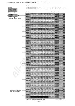
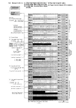
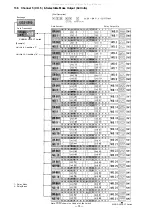
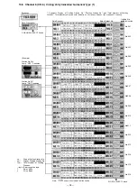
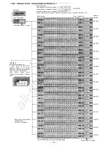
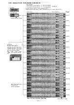
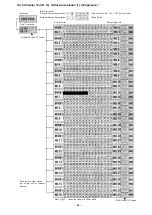
13-13  Channel 13 (CH. 13) Destination Indication (2)

(Dial  Operation)

• Registration  of  Personal  Number

• Cancellation  of  Personal  Number

Personal  Number:  Max. 32 persons  (No.1000~1031)

Station  Number  which  shows  Person's  Destination:  Max.  32  stations  (No.201~232)

Data Receiver

Relay  Output  No.

WORD SELECT Switch

Each  Relay Output shows

"Station No. of
Person's  Destination"

EXAMPLE 

I

Indication Panel-lamp on.

A  person  "No.1022"  registers  his
Personal  Number  at  the  station
"No.216", then the Relay contact
"No.216" turns into "Make".

Each 

Relay 

Output 

shows

"Station  No.  of  Person's  Destina-

tion"

CHANNEL SELECT Switch

Date Transmitter

Exchange

Personal

Number

No.1016

No.1017

No.1018

No.1019

No.1020

No.1021

No.1022

No.1023

No.1024

No.1025

No.1026

No .1027

No.1028

No. 1029

No.1030

No.1031

Note:

shows the Head of a Slide Switch

— 83 —

All manuals and user guides at all-guides.com

Summary of Contents for EXES 6000 CP-66

Page 1: ...ssing Unit for Single Exchange System or Tie line System INSTALLATION HAND BOOK CP 66 Toa Electric Co Ltd KOBE JAPAN INTERCOM SYSTEM TOA EXES 6OOO INTERCOM SYSTEM All manuals and user guides at all gu...

Page 2: ...telephone line for city pager 28 48 6 26 Fixedspeeddialling 29 49 Function Group G 6 27 Handset s t a t i o n 30 50 6 28 Stations Allowed Access to outgoing phone call 31 51 6 29 Stations Allowed Acc...

Page 3: ...uch additional function requires the following 1 Connection of the additional equipment as required 2 Selection of functions which satisfy your needs and setting up these functions in the respective e...

Page 4: ...ed 3 exchanges Tie lined EX 610 EX 620 EX 630 EX 610 EX 620 EX 630 EX 610 EX 620 EX 630 I Maximum number of links within one s own exchange 12 16 16 12 1 16 1 16 1 12 1 16 1 16 1 Number of links betwe...

Page 5: ...dialing operation When the Tie line system consists of either the EX 610 and EX 630 or the EX 620 and EX 630 When no personal Nos are provided Type of exchange EX 1 Single A EX 2A EX 3A B EX 2B EX 3B...

Page 6: ...r J12 Note 1 Any combination of tie line links between exchanges A and B is possible Note 2 Mount only one Tie line Interface unit when the number of tie line links is within 8 2 Wiring for tie line c...

Page 7: ...E2 and E3 to determine the type of exchange EX 1 EX 2A 28 EX 3A 3B 3C See 4 CP 66 DIP switches for Function Selection P14 2 If some tie line links are left idle set the corresponding DIP switch es to...

Page 8: ...630 YR 810 for stations YR 801 for Tie line for 128 stations BX 620 The cables between the exchanges 4 wires x 8 links Terminal board for 128 stations BX 620 YR 801 for Tie line YR 810 for stations Th...

Page 9: ...R 810 for stations Exchange A BX 620 T1 Exchange B BX 620 T1 YR 810 for stations YR 810 for stations YR 801 for Tie line Terminal board for 128 stations BX 620 YR 810 for stations YR 801 for Tie line...

Page 10: ...d following instructions carefully to ensure proper operation of the CP 66 8 We suggest you replace the soldered button batteryGB50 3FA1 115 42 031 9 with the new one according to the following list t...

Page 11: ...e B No 470 400 Exchange C No 740 700 2 lf there is any error in CMOS memory you hear calling tone instead of confirmation tone Dial operation from station No 200 1 Initial programming of the exchange...

Page 12: ...he CP OC and HC are working normally the HC s indication lamps of LINE BUSY LINE ADDRESS and SIGNAL CODE go out When any of the lamps remains lit it is possible that any of the CIP OC or HC is faulty...

Page 13: ...exchange making the call As Fig 1 and Fig 2 show in the exchanges which make calls the DL Link Number corresponds with Tl Tie line Link Number In the exchange which is called the Tie line Link Number...

Page 14: ...1 2 3 4 5 6 7 8 9 10 11 12 13 14 15 0 1 2 3 4 5 6 7 0 1 2 3 4 5 6 7 8 9 10 11 12 13 14 15 8 9 10 11 12 13 14 15 Fixed by Cable Connec tion between Exchanges After power switch is on Links are used in...

Page 15: ...l operation Personal number paging or call Paging response dial operation Paging amp delay remote operation Unavailable Unavailable Unavailable 45 Call Unavailable Available Available Available 21 Pag...

Page 16: ...s switch off can not perform all call paging 4 If the small digit number is selected the function can be operated without pressing the figure enclosed in parenthesis in the following example Example 5...

Page 17: ...Decimal Digits Output Secretary Transfer Master Sub Group Hunting Paging Response Paging Priority Group Blocking of Each Group Group of Calling Party Indication Func tion Code 40 41 42 430 431 45 46...

Page 18: ...se voice call Stations Allowed to refuse priority interruption Stations Allowed Access to zone paging Stations Allowed to refuse station paging Personal Number Single Digit Dialing Remote Response Fun...

Page 19: ...before the disconnection Pager call output digit selection Pager call function code output mode selection The number of digits in length may be selected to call a pager Function code transmission ord...

Page 20: ...Zone The Last Station No of the Zone Group Blocking Establishment of Each Group Group No 1 8 The First Station No of the Group The Last Station No of the Group Group of Calling Party Indication Group...

Page 21: ...to 40 digits Handset station Station No ON OFF 1 0 Restricted outgoing call Station No ON OFF 1 0 Restricted incoming call Station No ON OFF 1 0 Automatic pager transfer Station No ON OFF 1 0 Door st...

Page 22: ...hed Return NOTES 1 To allow all the stations to have this function Touch Confirmation tone will be heard Be sure to depress the key steadily 2 To release at one time the data programmed into all the s...

Page 23: ...hed Return NOTES 1 To allow all the stations to have this function Touch Confirmation tone will be heard Be sure to depress the key steadily 2 To release at one time the data programmed into all the s...

Page 24: ...turn NOTES 1 To allow all the stations to have this function Touch Confirmation tone will be heard 3 Re start at Step 1 when mis dialing occures All other registrations remain valid 4 Dial 2 digits wh...

Page 25: ...d Return NOTES 1 To allow all the stations to have this function Touch Confirmation tone will be heard Be sure to depress the key steadily 2 To release at one time the data programmed into all the sta...

Page 26: ...the key steadily 2 To release at one time the data programmed into all the stations for this function Touch Confirmation tone will be heard 6 5 AUTOMATIC ACCESS TO PAGING FUNCTION CODE 54 AUTOMATIC AC...

Page 27: ...200 programming for Function Code 54 is required 4 Call to Master Station from Handset Station or from Hands free Handset Station The TL 600S handset or handsfree handset substation can be registered...

Page 28: ...Release finished Return NOTES 1 To allow all the stations to have this function Touch Confirmation tone will be heard Be sure to depress the key steadily 2 To release at one time the data programmed i...

Page 29: ...finished Return NOTES 1 To allow all the stations to have this function Touch Confirmation tone will be heard Be sure to depress the key steadily 2 To release at one time the data programmed into all...

Page 30: ...ation tone Release finished Return NOTES 1 To allow all the stations to have this function Touc h Confirmation tone will be heard Be sure to depress the key steadily 2 To release at one time the data...

Page 31: ...nished Return NOTES 1 To allow all the stations to have this function Touch Confirmation tone will be heard Be sure to decrease the key steadily 2 To release at one time the data programmed into all t...

Page 32: ...ation tone Release finished Return NOTES 1 To release at one time the data programmed into all the stations for this function Touch Confirmation tone will be heard 2 Re start at Step 1 when mis dialin...

Page 33: ...tation No Touch Sub Station No Confirmation tone Release finished Return NOTES 1 To release at one time the data programmed into all the stations for this function Touch Confirmation tone will be hear...

Page 34: ...inished YES Return NOTES 1 To release at one time the data programmed into all the stations for this function Touch Confirmation tone will be heard 2 Re start at Step 1 when mis dialing occurs All oth...

Page 35: ...this function 4 Also dial 2 digits 01 to 07 to programme the system having paging zones 1 to 7 Ex Zone No 7 5 When Paging Response Without Zone Number mode is selected by the DIP Switch SW C 7 this re...

Page 36: ...istration finished YES Return NOTES 1 To release at one time the data programmed into all the groups for this function Touch Confirmation tone will be heard 10 times 2 Re start at Step 1 when mis dial...

Page 37: ...ration finished YES Return NOTES 1 To release at one time the data programmed into all the groups for this function Touch Confirmation tone will be heard 10 times 2 Re start at Step 1 when mis dialing...

Page 38: ...e No Touch Combination Paging Zone No Touch Confirmation tone NO Release finished YES Return NOTES 1 To release at one time the data programmed into all the Zones for this function Touch Confirmation...

Page 39: ...ew Registration finished YES NO Release YES Calling Group No Touch Calling Group No Touch Confirmation tone NO Release finished YES Return NOTES 1 To release at one time the data programmed into all t...

Page 40: ...tone NO New Registration finished NO YES Release YES Paging Zone or Combination Paging Zone Touch Paging Zone Combination Paging Zone Touch Confirmation tone NO Release finished YES Return NOTES 1 To...

Page 41: ...n No Programmed Station No Touch 1 2 Hardwired Station No Programmed Station No Touch 1 2 Confirmation tone NO New Registration finished YES NO Release YES Hardwired Station No Touch 1 Hardwired Stati...

Page 42: ...irmation tone will be heard 10 times 2 Any one Programmed Station No cannot be assigned to more than one Hardwired Station 3 Dial 2 digits when programming the station for 2 digit dialling Dial last 3...

Page 43: ...620 630 and connected to the remote extension system the Tie line interface provides the system with mutual paging calling and conversation functions 3 Numbering schedule external interfaces Before t...

Page 44: ...e NO Registered YES Number of digits for trunk seizure operation Double digit NO YES Trunk seizure operation 1st line No Last line No Touch Trunk seizure operation 1st line No Last line No Touch Confi...

Page 45: ...e NO Registered YES Number of digits for trunk seizure operation Double digit NO YES Trunk seizure operation 1st line No Last line No Touch Trunk seizure operation 1st line No Last line No Touch Confi...

Page 46: ...Trunk sezure Incoming call pick up 1st line No Last line No Touch Trunk sezure Incoming call pick up 1st line No Last line No Touch Confirmation tone NO Registered YES Return NOTES 1 To clear registra...

Page 47: ...e NO Registered YES NO Number of digits for trunk seizure operation Double digit YES Trunk seizure operation 1st line No Last line No Touch Trunk seizure operation 1st line No Last line No Touch Confi...

Page 48: ...will be heard 2 Re start at Step 1 when mis dialing occurs All other registrations remain valid 3 Switch C 1 must be ON to employ this function 4 Also dial 2 digits 01 to 07 to programme the system h...

Page 49: ...unk seizure operation Double digit YES Trunk seizure operation 1st line No Last line No 20 99 00 15 00 15 Touch Trunk seizure operation 1st line No Last line No 20 99 00 15 00 15 Touch Confirmation to...

Page 50: ...peed dialling Touch Confirmation tone will be heard 10 times 2 Re start Step 1 when mis dialing occurs All other registrations remain valid 3 A maximum of 10 telephone numbers may be registered for Sp...

Page 51: ...ll the stations to have this function Touch Confirmation tone will be heard 10 times Be sure to depress the key steadily 2 To release at one time the data programmed into all the stations for this fun...

Page 52: ...make outgoing telephone call OFF Touch Confirmation tone NO Release finished YES Return NOTES 1 To allow all the stations to have this function Touch Confirmation tone will be heard 10 times Be sure...

Page 53: ...to receive incoming call directly OFF Touch Confirmation tone NO Release finished YES Return NOTES 1 To allow all the stations to have this function Touch Confirmation tone will be heard 10 times Be s...

Page 54: ...turn NOTES 1 To allow all the stations to have this function Touch Confirmation tone will be heard 10 times Be sure to depress the key steadily 3 Re start at Step 1 when mis dialing occures All other...

Page 55: ...all the stations to have this function Touch Confirmation tone will be heard 10 times Be sure to depress the key steadily 2 To release at one time the data programmed into all the stations for this fu...

Page 56: ...shed YES Return NOTES 1 To allow all the stations to have this function Touch Confirmation tone willbe heard 10 times Be sure to depress the key steadily 2 To release at one time the data programmed i...

Page 57: ...one NO Release finished YES Return NOTES 1 To allow all the stations to have this function Touch Confirmation tone will be heard 10 times 3 Re start at Step 1 when mis dialing occures All other regist...

Page 58: ...ease finished YES Return NOTES 1 To allow all the stations to have this function Touch Confirmation tone will be heard 10 times Be sure to depress the key steadily 2 To release at one time the data pr...

Page 59: ...to make Priority Station Paging OFF Touch Confirmation tone NO Release finished YES Return NOTES 1 To allow all the stations to have this function Touch 10 times Be sure to depress the key steadily 2...

Page 60: ...Confirmation tone will be heard Clears function group D 8 Confirmation tone will be heard Clears function group E 9 Confirmation tone will be heard Clears personal numbers single digit dial numbers a...

Page 61: ...0 600 700 800 900 0 No call tone 1 Single tone 0 2 second 2 Trill tone 0 3 second 0 No pre announcement tone 1 Pre announcement tone 1 second 2 Pre announcement tone 2 seconds 1st digit of station No...

Page 62: ...tput Stations Allowed Access to Make Break Output Stations Allowed Access to 1 8 Select or Decimal Output Stations Allowed Access to 4 Decimal Digits Output Secretary Station No 1 Master Station No 1...

Page 63: ...Paging Response Table Paging Zone Department First Station No No Last Station No Function Code 70 Exchange A Tie line Single Exchange 62 All manuals and user guides at all guides com...

Page 64: ...nnunciation Calling Party Indication etc Refer to 12 Expla nation of Data Transmitting Unit Output Data 4 The DT E60 sends out 512 bit data 16 bit x 32 words to control relays on Data Receiving Unit D...

Page 65: ...DATA TRANSMITTING AND RECEIVING UNITS CHANNEL SELECT Switch Exchange Data Transmitter Data Receiver Note shows the Head of a Slide Switch WORD SELECT Switch Relay Output No 64 All manuals and user gu...

Page 66: ...0 SYSTEM DIAGRAM OF DATA TRANSMITTING AND RECEIVING UNITS Single Exchange Enlarged Block Diagram of Calling Party Indication 65 66 All manuals and user guides at all guides com a l l g u i d e s c o m...

Page 67: ...11 SYSTEM DIAGRAM OF DATA TRANSMITTING AND RECEIVING UNITS Tie line System 68 67 All manuals and user guides at all guides com...

Page 68: ...ie line Interface Unit 69 YR 802 or YR 806 YR 803 YR 803 YR 803 YR 803 YR 803 YR 803 YR 803 YR 803 YR 803 YR 803 Terminal Board Stations YR 810 Data Transmitting Unit All manuals and user guides at al...

Page 69: ...hen a station with a Display Board is called calling party number is over and also when the called station is busy or in privary Calling party indication lamp type This function permits a maximum of 2...

Page 70: ...13 EXPLANATION OF DATA RECEIVING UNIT OUTPUT DATA 13 1 Channel 1 CH 1 Make Break Output Dial Operation Relay Make XXX 000 511 512 contacts XX 00 99 100 contacts Relay Break Relay Output No Data Recei...

Page 71: ...al Operation Data Receiver Relay Make min 1 ms max 2ms XXX 000 499 500 contacts XX 00 49 50 contacts Relay Output No Each Relay Output shows RElay Contact Number Note shows the Head of a Slide Switch...

Page 72: ...2 Decimal Output 3 8 Selectable Make Output Unit No Condition No Unit No 8 Condition 9 Bindary Negative Logic Output Unit No 4 Condition 1 Unit No 6 Condition 8 1 Relay Make 0 Relay Break 4 Pager Con...

Page 73: ...NEL SELECT Switch Unit No Condition No Relay Output No Example Unit No 24 Condition 3 Binary Negative Logic 3 Unit No 48 Condition 0 Binary Negative Logic 0 1 Relay Make 0 Relay Break Note shows the H...

Page 74: ...T Switch 13 5 Channel 5 CH 5 8 Selectable Make Output 64 Units 1 Relay Make 0 Relay Break Exchange Data Transmitter Data Receiver Dial Operation Relay Output No WORD SELECT Switch shows the Head of a...

Page 75: ...stations Channel 32 stations 2 Channel 13 6 Channel 6 CH 6 Calling Party Indication Numerical Type 1 No 201 No 202 No 203 No 204 No 205 No 206 No 207 No 208 No 209 No 210 No 211 No 212 No 213 No 214 N...

Page 76: ...0 No 231 No 232 7 Segments Display of Calling Station No Waiting Station No and Total Number of Waiting Stations Total Number of Station with Indications 16 stations Channel 32 stations 2 Channel Stat...

Page 77: ...ons 2 Stations Channel 8 Stations 4 Channels Total Number of Calling Stations Max 256 Stations Each Indication Relay Output No Station No with Indication Data Receiver Exchange Data Transmitter CHANNE...

Page 78: ...ons 2 Stations Channel 8 Stations 4 Channels Total Number of Calling Stations Max 256 Stations Each Indication Station No with Indication Relay Output No Data Receiver Exchange Data Transmitter CHANNE...

Page 79: ...tions 2 Stations Channel 8 Stations 4 Channels Total Number of Calling Stations Max 256 Stations Each Indication Station No with Indication Relay Output No Data Receiver Exchange Data Transmitter CHAN...

Page 80: ...ations 2 Stations Channel 8 Stations 4 Channels Total Number of Calling Stations 256 Stations Each Indication Exchange Data Transmitter CHANNEL SELECT Switch Data Receiver Relay Output No Station No w...

Page 81: ...Indication Panel lamp on A person No 1006 registers his Personal Number at the station No 216 then the Relay contact No 216 turns into Make Each Relay Output shows Station No of Person s Destina tion...

Page 82: ...ation No of Person s Destination EXAMPLE I Indication Panel lamp on A person No 1022 registers his Personal Number at the station No 216 then the Relay contact No 216 turns into Make Each Relay Output...

Page 83: ...ersonal Number Cancellation Relay Make XXX 000 503 504 contacts Relay Break Relay Output No Date Receiver Data Transmitter CHANNEL SELECT Switch WORD SELECT Switch shows the Head of a Slide Switch Eac...

Page 84: ...mber Cancellation Relay Make XXX 000 499 500 Contacts Relay Break Relay Output No Data Receiver Exchange Data Transmitter CHANNEL SELECT Switch Each Relay Output shows last 3 digits xxx of Personal Nu...

Page 85: ...133 21 174 8 All manuals and user guides at all guides com...

Reviews: