background image

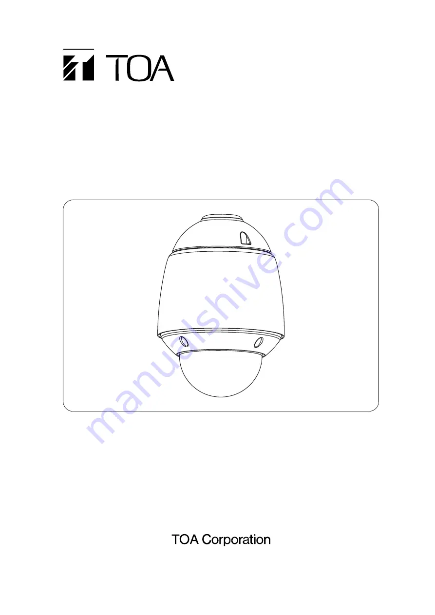
Thank you for purchasing TOA’s Outdoor Combination Camera. Please carefully follow the instructions in
this manual to ensure long, trouble-free use of your equipment.

OUTDOOR COMBINATION CAMERA

C-CC714 NT

C-CC714 PL

C-CC764 NT

C-CC764 PL

C-CC774 NT

C-CC774 PL

INSTALLATION MANUAL

Summary of Contents for C-CC714 NT

Page 1: ...Combination Camera Please carefully follow the instructions in this manual to ensure long trouble free use of your equipment OUTDOOR COMBINATION CAMERA C CC714 NT C CC714 PL C CC764 NT C CC764 PL C C...

Page 2: ...ing Switch DIP switch 2 No 1 2 13 7 3 3 OSD Switch DIP switch 2 No 3 13 7 3 4 Communication Method Selector Switch DIP switch 2 No 6 13 7 3 5 Termination Switch DIP switch 2 No 8 13 7 3 6 Firmware Upd...

Page 3: ...et Doing otherwise may result in the unit falling down and causing personal injury and or property damage Only use the unit s dedicated mounting hardware The use of mounting hardware not designated co...

Page 4: ...servicing to your nearest TOA dealer Do not insert nor drop metallic objects or flammable materials in the ventilation slots of the unit s cover as this may result in fire or electric shock Do not to...

Page 5: ...e all these cameras are integrated with a weather resistant outdoor use housing and a built in fan heater they can be freely used outdoors as well 3 FEATURES Digital signal processing realizes high re...

Page 6: ...ect sunlight could cause the CCD s color filter to deteriorate leading to image discoloration When the C CC774 is recommended that presets be entered into the memory 10 minutes or more after the power...

Page 7: ...Safety UL Certification does not cover the performance or reliability of the security hardware and security operating software UL MAKES NO REPRESENTATIONS WARRANTIES OR CERTIFICATIONS WHATSOEVER REGAR...

Page 8: ...8 1 2 3 4 5 6 Housing Appearance 13 14 15 16 18 19 17 20 19 10 12 9 9 9 9 11 11 7 8 9 9 Housing Bottom Camera Unit Top Camera Unit Bottom 5 NOMENCLATURE Appearance Camera Unit Appearance...

Page 9: ...6 DIP switch SW1 17 DIP switch SW2 18 DIP switch SW3 19 Camera unit mounting hole 20 Safety wire for camera unit 21 Wall mounting bracket 22 Hook to connect safety wire for housing 23 Suspension brack...

Page 10: ...tion of the power supply cables video output cables or multicore cables from water System controller Multi switcher Monitor Insulate with vinyl tape 1 2 3 4 5 6 7 8 Power cable Connects to the power s...

Page 11: ...connectable to a pair of RS 485 lines from termination to termination is 32 units including the Remote Controller The maximum cable length connecting each terminal is 1 2 km in total The camera may n...

Page 12: ...SW1 DIP SW2 DIP SW3 Note Set the unused DIP switches to the OFF position If the DIP switches are not set correctly the camera does not operate correctly DIP SW1 DIP SW2 DIP SW3 No 1 No 2 No 3 No 4 No...

Page 13: ...2 No 6 Chooses the RS 485 communication method from Type A used with the C RM500 Remote Controller and Type B Set the switch to the OFF position to choose Type A and to the ON position to choose Type...

Page 14: ...4 5 6 7 8 ON 1 2 3 4 5 6 7 8 ON 1 2 3 4 5 6 7 8 ON 1 2 3 4 5 6 7 8 9 25 41 57 ON 1 2 3 4 5 6 7 8 ON 1 2 3 4 5 6 7 8 ON 1 2 3 4 5 6 7 8 ON 1 2 3 4 5 6 7 8 10 26 42 58 ON 1 2 3 4 5 6 7 8 ON 1 2 3 4 5 6...

Page 15: ...3 4 5 6 7 8 ON 1 2 3 4 5 6 7 8 ON 1 2 3 4 5 6 7 8 ON 1 2 3 4 5 6 7 8 73 89 105 121 ON 1 2 3 4 5 6 7 8 ON 1 2 3 4 5 6 7 8 ON 1 2 3 4 5 6 7 8 ON 1 2 3 4 5 6 7 8 74 90 106 122 ON 1 2 3 4 5 6 7 8 ON 1 2 3...

Page 16: ...3 4 5 6 7 8 ON 1 2 3 4 5 6 7 8 ON 1 2 3 4 5 6 7 8 ON 1 2 3 4 5 6 7 8 137 153 169 185 ON 1 2 3 4 5 6 7 8 ON 1 2 3 4 5 6 7 8 ON 1 2 3 4 5 6 7 8 ON 1 2 3 4 5 6 7 8 138 154 170 186 ON 1 2 3 4 5 6 7 8 ON...

Page 17: ...248 ON 1 2 3 4 5 6 7 8 ON 1 2 3 4 5 6 7 8 ON 1 2 3 4 5 6 7 8 ON 1 2 3 4 5 6 7 8 201 217 233 249 ON 1 2 3 4 5 6 7 8 ON 1 2 3 4 5 6 7 8 ON 1 2 3 4 5 6 7 8 ON 1 2 3 4 5 6 7 8 202 218 234 250 ON 1 2 3 4...

Page 18: ...Perform presetting beforehand when controlling the camera using the RS 485 refer to p 11 Camera Settings 8 2 Installation Method The camera can be mounted on a wall a pole or be suspended from a ceili...

Page 19: ...bracket Use bolts nuts and washers that are appropriate for the wall s structure and composition Be sure to hang the safety wire first when installing the unit 2 Run the cables to be connected to the...

Page 20: ...top cover then hang the hook to the mounting bracket 3 Run the top cover through the pipe then connect cables Top cover Wall surface Safety wire Housing Insulate the terminals by wrapping the vinyl i...

Page 21: ...housing against the pipe 4 After confirming the housing direction push the housing up then tighten 2 safety screws Top cover Safety screw Safety screw Housing Align the hole positions Figure viewed f...

Page 22: ...rk 6 Using the supplied 3 hexagon socket screws attach the top cover 1 to the housing Hexagon socket screw M4 x 8 supplied with Hexagon socket screw M4 x 8 supplied with Aligning the positioning marks...

Page 23: ...view of the housing Camera unit 1 2 mark Duct Note Insert the camera unit in an oblique direction in the order of 1 to 2 keeping away from the duct of the housing Push the camera unit straight up clo...

Page 24: ...l it is attached to the housing correctly Mounting it at an angle may cause damage to the camera unit Cross sectional view of the housing Camera unit Mount straight Cross sectional view of the housing...

Page 25: ...the camera unit to the base unit Camera unit mounting screw Camera unit mounting screw 11 Attach the dome cover Slide down the dome cover s screw head through the housing suspension fitting s slot Ha...

Page 26: ...Align the dome cover s 4 screws with the hexagon head sleeves inside the housing Note Be sure to attach the dome cover after sliding down its screw head through the housing suspension fitting s slot s...

Page 27: ...mounting bands into the pole mounting bracket s slots then attach the band to a pole C BC711PM optional YS 60B Mounting Band optional Hexagon head bolt M8 M10 or W 3 8 2 Attach the wall mounting brack...

Page 28: ...the weight of the units 1 Make a cable entry hole of 50 100 mm on a ceiling Hole diameter 50 100mm C BC711P optional 2 Attach the suspension bracket to a ceiling Note Bolts etc are not supplied with t...

Page 29: ...or combination camera Dedicated Remote controller Note Combination cameras and outdoor combination cameras can be used in free combinations When a camera fixed installation 1 is used in combinations t...

Page 30: ...ion 12 x zooming One push stop AF continuous 22 x f 4 0 88 mm 22 times Horizontal 47 3 W 2 2 T Vertical 36 5 W 1 7 T F 1 6 W 3 8 T WIDE end to TELE end Approx 1 3 s preset operation Approx 2 4 s manua...

Page 31: ...zooming One push stop AF continuous 23 x f 3 6 82 8 mm 23 times Horizontal 54 W 2 5 T Vertical 41 6 W 1 9 T F 1 6 W 3 7 T WIDE end to TELE end Approx 1 5 s preset operation Approx 2 9 s manual operat...

Page 32: ...e push stop AF continuous 35 x f 3 4 119mm 35x Horizontal 55 8 W 1 7 T Vertical 43 3 W 1 3 T F 1 4 W 4 2 T WIDE end to TELE end Approx 2 s preset operation Approx 3 2 s manual operation Panning Endles...

Page 33: ...e push stop AF continuous 35 x f 3 4 119mm 35x Horizontal 55 8 W 1 7 T Vertical 43 3 W 1 3 T F 1 4 W 4 2 T WIDE end to TELE end Approx 2 s preset operation Approx 3 2 s manual operation Panning Endles...

Page 34: ...ONTROLLER Software installation manual 1 Hexagon socket screw M4 x 8 3 Optional Products Wall Mounting Bracket C BC711W Suspension Bracket C BC711P Pole Mounting Bracket C BC711PM Mounting Band YS 60B...

Page 35: ...35...

Page 36: ...133 05 406 0A...

Reviews: