


11
MULTIPLE APPLIANCE INTERLOCKS
To interlock with one additional 24/115 VAC heater, add the MAC1E. It is a stripped down auxiliary board version of the UC1 and
is powered by and communicates with the UC1 through a factory wired whip.
To interlock more than two 24/115 VAC heaters, add the MAC4E for a total of up to 5 heaters. It is powered by and communicates
with the UC1 through a factory wired whip. Consult factory for installations with more than 5 heaters.
MPCI OPERATION AND INTERLOCK CONFIRMATION
Establish 120 VAC supply power to the MPCI and switch MPCI internal power switch to the ON position.
Activate one of the connected heaters.
Validate that the Status LED’s of the UC1 interlock board light and operational sequences occur as described on Page 8.
Remove the pneumatic tubing from the sampling tube to disrupt the connection to the PSA-1 and the MPCI.
After 10 seconds the UC1 interlock control should disrupt the circuit from terminal 4 to the burner(s).
As long as there is a call for heat, the UC1 will continue to power the MPCI Pressure Control for 10 minutes. (If the pressure set
point is not reached after 10 minutes, the UC1 will disrupt power to the Pressure Control and go into a hard lockout. Reset UC1 by
removing call for heat or turning off the MPCI internal power switch.
The Pressure Control will continue to output a 1-10 VDC signal to speed the fan up.
When the output reaches 10 VDC, a 10 second delay will occur and then the Pressure Control Alarm Circuit will activate, powering
the MPCI external RED light with audible alarm as well as any external alarm or BMS that are wired to the alarm circuit.
Reconnect the pneumatic tubing to the sampling tube.
The safety circuit will reset when the pressure set point is once again sensed.
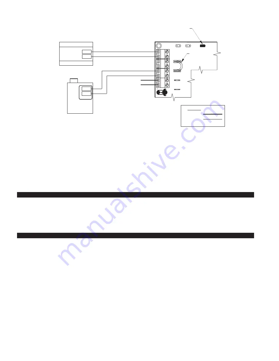
UC1 / MAC-SERIES CONTROL CONNECTED TO DRY
CONTACTS OF BOILER STAGING OR ZONE CONTROL
BOILER BURNER
CONTROL
REMOVE
CALL JUMPER
RED JUMPER POSITION MUST
BE SET TO THE "DRY" POSITION.
IMPORTANT:
SUPPLY
115 VAC
50/60 Hz
GROUND
CRIMP GROUND WIRE TO GROUNDING
SPADE TERMINAL IN ELECTRICAL BOX.
IMPORTANT:
IMPORTANT:
XN
UNIVERSAL CONTROLLER
115 VAC
LEGEND:
XL
J1
J2
115V
24V
T
T
BOILER STAGING
OR ZONE CONTROL
T
T
INTERLOCK
WIRING
DRY
A B 1 2 3 4 L N
R
1. Connect TT from staging control to the A & B terminals of the UC1/MAC-Series Interlock associated with that boiler.
2. Connect terminals 3 & 4 of the UC1/MAC-Series Interlock associated with that boiler to the boiler’s TT terminals.
3. Move the RED plastic jumper from the 115V pins to the DRY position.
4.
Important:
Remove the call Jumper wire from the J1 & J2 terminals of the UC1 circuit board.
TT closure of boiler staging or zone control completes the low voltage circuit between A & B of the UC1 / MAC-Series Interlock
Controls, activating the Pressure Control. When the Fan Proving switch closes the circuit is completed between terminals 3 & 4,
closing the circuit at TT of the boiler’s actuation control.
5. The PSA-1 Fan Prover is only used for Draft applications, not Combustion Air applications. Wire PSA-1 prover leads to
P1 and P2 PROVER terminals in MPCI. Prover leads are non polarity sensitive.
NOTE:
If burner safety control goes out on lockout, the Venter will continue to run as long as a call for heat is present.