background image

42


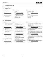
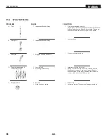
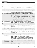
troubleshooting

ProMark

proBlem 


A.  Spitting gun


B.  Gun will not shut off


C.  Gun does not spray

proBlem 


A.  Pump delivers on upstroke only 

or goes up slowly and down fast 

(commonly called downstroke 

dive)


B.  Pump delivers on down stroke 

only or goes up fast and down 

slowly


C.  Pump moves up and down fast, 

delivering material

  D.  Pump moves up and down 

slowly when spray gun is shut 

off


E.  Not enough fluid pressure at 

gun


F.  Pump chatters on up or down 

stroke

cAuSe


1.  Air in system


2.  Dirty gun


3.  Needle assembly out of adjustment


4.  Broken or chipped seat


1.  Worn or broken needle & seat


2.  Needle assembly out of adjustment


3.  Dirty gun


1.  No paint


2.  Plugged filter or tip


3.  Broken needle in gun

cAuSe


1.  Lower foot valve ball is not seating due to 

trash or wear


2.  Material too viscous to siphon.


3.  Air leaking in on siphon side or damaged 

siphon hose. Siphon may be too small for 

heavy material.


1.  Upper ball is not seating due to trash or wear


2.  Lower packing set is worn


1.  Material container is empty or material is too 

thick to flow through siphon hose


2.  Bottom ball stuck to foot valve seat


3.  Siphon hose is kinked or loose


1.  Loose connections. Bleed valve is open 

partially or bleed valve is worn. Lower 

packing seat is worn.


2.  Upper and/or lower ball not seating


1.  Spray tip is worn


2.  Outlet filter or gun filter is clogged


3.  Low voltage and/or inadequate amperage


4.  Hose size or length is too small or too long


1.  Solvent has caused upper packing to swell

SoluTIoN


1.  Inspect connections for air leaks.


2.  Disassemble and clean.


3.  Inspect and adjust.


4.  Inspect and replace.

  1. Replace.

  2. Adjust.

  3. Clean.


1.  Check fluid supply.

  2. Clean.

  3. Replace.

SoluTIoN


1.  Remove foot valve assembly. Clean and inspect. Test 

foot valve by filling with water; if ball fails to seal the 

seat, replace ball.


2.  Thin material — contact manufacturer for proper 

thinning procedures.


3.  Tighten all connections between pump and paint 

container. If damaged, replace. Switch to larger diameter 

siphon set.


1.  Check upper seat and ball with water. If ball fails to seal, 

replace seat.


2.  Replace packing set if worn.


1.  Refill with new material. If too thick, remove siphon 

hose, immerse fluid section in material, and start pump 

to prime.  Add thinner to material.  Change to bigger 

siphon set.  Open bleed valve to  remove air and restart 

pump.


2.  Remove foot valve. Clean ball and seat.

  3. Straighten.


1.  Check all connections between pump and gun. Tighten 

as necessary. If material is flowing from bleed hose, close 

bleed valve or replace, if necessary. Should none of the 

above be evident, replace lower packing.


2.  Reseat balls by cleaning.

  1. Replace.


2.  Clean or replace filter.


3.  Check electrical service.  Correct as required.


4.  Increase hose size to minimize pressure drop through 

hose and/or reduce hose length.


1.  Replace packing.

TrouBleShooTINg

9.1 

AIrleSS guN

9.2 

fluID SecTIoN

Summary of Contents for 200

Page 1: ...s 98 2 1016 Form No 0153705A D Betriebsanleitung 46 F Mode d emploi 90 OPERATING MANUAL MMA Methyl Methacrylate STriping system MMA METHYLMETHACRYLAT MARKIERUNGSSYSTEM SYSTÈME DE MARQUAGE AU MÉTHACRYLATE DE MÉTHYLE ...

Page 2: ...orm the doctor about the coating material or solvent used The operating instructions state that the following points must always be observed before starting up 1 Faulty units must not be used 2 Secure Titan spray gun using the trigger lock on the trigger 3 Ensure that the unit is properly earthed 4 Check allowable operating pressure of high pressure hose and spray gun 5 Check all connections for l...

Page 3: ... Handling the high pressure hose_________________29 7 Cleanup_______________________________ 30 7 1 Special cleanup instructions for use with flammable solvents____________________________30 7 2 Cleaning the sprayer___________________________30 7 3 Cleaning the outside of the sprayer_______________30 7 4 Cleaning the airless spray gun___________________31 8 Maintenance__________________________ 32...

Page 4: ...serious injury and possible amputation Do not treat a spraying injury as a harmless cut In caseofinjurytotheskinthroughcoatingmaterials or solvents consult a doctor immediately for quick and expert treatment Inform the doctor about the coating material or solvent used PREVENTION NEVER aim the gun at any part of the body NEVER allow any part of the body to touch the fluid stream DO NOT allow body t...

Page 5: ... only in well ventilated area Keep a good supply of fresh air moving through the area to keep the air within the spray area free from accumulation of flammable vapors Keep pump assembly in well ventilated area Do not spray pump assembly Do not fill fuel tank while engine is running or hot shut off engine and allow to cool Fuel is flammable and can ignite or explode if spilled on a hot surface Elim...

Page 6: ...ic oil must be disposed of in an environmentally friendly way 1 3 Gasoline Engine Safety 1 Gas engines are designed to give safe and dependable service if operated according to instructions Read and understand the engine manufacturer s Owner s Manual before operating the engine Failure to do so could result in personal injury or equipment damage 2 To prevent fire hazards and to provide adequate ve...

Page 7: ...l gasoline mixture Avoid getting dirt dust or water in the fuel tank Gasolines Containing Alcohol If you decide to use a gasoline containing alcohol gasohol be sure its octane rating is at least as high as that recommended by the engine manufacturer There are two types of gasohol one containing ethanol and the other containing methanol Do not use gasohol that contains more than 10 ethanol Do not u...

Page 8: ...otbetaken in or the performance of the unit is to low the material must be diluted in accordance with the manufacturer s instructions i Attention Make sure when stirring up with motor driven agitators that no air bubbles are stirred in Air bubbles disturb when spraying and can in fact lead to interruption of operation Coating materials with abrasive materials These have a strong wear and tear effe...

Page 9: ...ally by the upwards movement of the piston The outlet valve is opened when the piston moves downward This movement draws material from the material container though the siphon hose and delivers it to the mixing block 6 where it is mixed with the BPO Benzoyl Peroxide and delivered to the spray gun s The hydraulic motor movement also provides power and movement to the BPO pump 7 which in turn provid...

Page 10: ...10 description of unit ProMark 3 2 System diagram FIGURE 2 2 5b 7 8 4a 5a 3 3a 4b 11a 4 5 9a 13 14 11 8a 12 10 6 11b 1 9 ...

Page 11: ...Arm The SmartArm allows the user to adjust the height of the spray gun s The gun holder devices at the end of the SmartArm allow the user to position each gun individually The SmartArm can retract pivot up for transport and storage 8 Air compressor The air compressor is powered by the gasoline engine and provides air pressure to the solvent flush and the bead dispenser a Air cylinder The air cylin...

Page 12: ...12 description of unit ProMark 3 3 System controls FIGURE 3 1 5 4 8 2 3 6 7 9 10 11 12 ...

Page 13: ...tem is ready to be flushed 6 BPO shutoff valve The BPO shutoff valve will cut off the flow of BPO to the mixing block when closed Usage note This should remain open during spraying and closed whenever performing a solvent flush 7 Spray material shutoff valve The spray material shutoff valve will cut off the flow of spray material to the mixing block when closed Usage note This should remain open d...

Page 14: ... key ignition turns the unit ON and starts the engine 6 Spray material pressure gauge Measures the spraying pressure of the spray material 7 Caster trigger Controls the front caster To lock the front caster in the straight line position squeeze then release the caster trigger and move the sprayer forward To allow free motion of the front caster squeeze and hold the caster trigger 8 Pressure contro...

Page 15: ... footages applied set spacing for the trace function view modify the setup screen and go to the run screen Whenever spraying the RUN screen will be displayed The Instant and Average mil of material applied current speed and the gallons of material applied will be shown Pressing F2 will reset the instant and average mils To exit out of the run screen and go to the menu screen press the Return to Ma...

Page 16: ... this procedure twice using the same measured distance travelling in the same direction If the encoder scale is the same for both tries the operator knows that the machine is properly calibrated and can be used for marking distances Pattern Trace screens At the Setup screen press Next to go to the Pattern Trace screen The trace pattern screen serves two functions the first is to set up the trace p...

Page 17: ...al Color option Selecting Metric will switch the unit to measure values in meters and liters parking lot layout From the Main Menu screen press the Parking Lot Layout button to get to the Parking Lot Layout screen From here the operator can choose one of the following options Measure Stalls used to determine the width of each stall Stripe Stalls Used to mark parking stalls Marker Layout for markin...

Page 18: ... up to eight distances press the Edit button in the upper right corner Press inside the Spacing box and manually enter in a distance for all the marks that you want use the up and down arrows to change Press the Copy button to copy the current spacing to the next marker Note that all distances are in feet to assign a width that is in inches divide the number by 12 to get the value in feet Example ...

Page 19: ...l enable the continuous spray but will not begin marking paint Paint will only begin coming out continuously when the operator has pressed the red switch on the right handle bar of the sprayer To take the machine out of continuous spray press the red switch again Operator should note that if the toggle switches on the enclosure are set to Skip the machine will only spray for the skip setting that ...

Page 20: ...y 5 9 l 1 56 gal CoolFlo Max tire pressure 0 2 MPa 2 bar 30 PSI Place of measurement 1 m distance from unit and 1 60 m above reverberant floor 120 bar 12 MPa operating pressure Operating Temperature This equipment will operate correctly in its intended ambient at a minimum between 10 C and 40 C Relative Humidity The equipment will operate correctly within an environment at 50 RH 40 C Higher RH may...

Page 21: ...ber sealing cap with the exhaust tube provided this can be found in the plastic bag containing the instruction manual and other literature 4 Remove the six 6 yellow filling caps on top of the battery 5 Fill the battery with electrolyte in each of the filling ports see Electrolyte specifications above Fill the battery to the upper level as indicated on the battery case Attention The electrolyte tem...

Page 22: ...not fill past here BPO valve 4 3 Filling the solvent flush tank Attention The ProMark system needs to be flushed with solvent whenever the system remains idle for more than 2 3 minutes otherwise the spray material BPO mixture will harden inside the mixing chamber hoses and spray guns rendering them inoperable Check the solvent flush level before each use It is a good idea to always keep extra solv...

Page 23: ... versa Spray tip size also affects line width If using a two gun system the guns can be placed side by side to create wider single lines or further apart to create narrower double lines Adjust the height of the spray gun by adjusting the various clamps vertically or horizonally or adjust vertically everything all at once by turning the SmartArm crank Bead dispenser gun configuration The bead dispe...

Page 24: ...lt that secures the pump piston to the pump arm 2 Replace the pump piston into the pump arm orifice that is suitable for your spraying job FIGURE 10 BPO BPO i BPO is provided to the mixture at a 98 2 spray material to BPO ratio 98 ounces spray mixture for every 2 ounces of BPO For every hole that the BPO pump piston is moved the BPO ratio is increased or decreased by 1 2 ounce 4 7 lubricate the pa...

Page 25: ...seriously damage the hydraulic system and will void the warranty 4 9 final checks 1 Check the engine oil level daily before starting the sprayer The gasoline engine oil level is determined by the engine manufacturer Refer to the engine manufacturer s service manual supplied with this sprayer 2 Make sure the sprayer is grounded earthed All sprayers are equipped with a grounding earthing chain which...

Page 26: ...New Sprayer i If this unit is new it is shipped with test fluid in the fluid section to prevent corrosion during shipment and storage This fluid must be thoroughly cleaned out of the system with mineral spirits before you begin spraying Attention Always keep the trigger lock on the spray gun in the locked position while preparing the system Refer to the spray gun instruction manual for trigger loc...

Page 27: ...e in the vertical position FIGURE 14 BPO tank valve 9 Make sure the BPO shutoff valve located near the mixing block is in the open position The valve handle should be in the horizontal position 10 Start the engine refer to section 5 1 11 While the engine is running remove the angled fitting that attaches the BPO hose to the mixing block with an adjustable wrench This is the hose marked in blue at ...

Page 28: ...ing the system Follow the steps in the next section 6 3 solvent flush Attention Follow these steps whenever stopping spraying foranyreason Thiswillpreventthespraymixture from setting up in the system and clogging it This solvent flush procedure also acts as a pressure relief procedure that will relieve the system of all pressure 1 Turn the pressure control knob located on the dashboard fully count...

Page 29: ...thout the proper tip guard 5 Rotate the tip handle back to its original position 6 Close the relief valve handle located on the high pressure filter and resume spraying Repeat this section if necessary i If after performing these steps multiple times the spray tip is still clogged perform a full solvent flush section 6 3 The spray tip may need to be replaced if clogging persists 6 5 Handling the h...

Page 30: ...rer for the recommended solvent 4 Place the bleed hose into a metal waste container 5 Set the pressure to minimum by turning the pressure control knob fully counterclockwise 6 Open the spray material shutoff valve on the high pressure filter 7 Start the engine see section 5 1 8 Allow the solvent to circulate through the sprayer and flush the paint out of the bleed hose into the metal waste contain...

Page 31: ...ent so that no coating material residue remains 3 Thoroughly clean the outside of the airless spray gun Intake filter in Airless spray gun 1 Pull the bottom of the trigger guard forward so that it comes loose from the handle assembly 2 Loosen and remove the handle assembly from the gun head 3 Pull the old filter out of the gun head 4 Slide the new filter tapered end first into the gun head 5 Place...

Page 32: ... filter assembly i Clean the filter regularly Dirty or clogged filters can greatly reduce filtering ability and cause a number of system problems including poor spray patterns clogged spray tips etc Cleaning Fig 19 To clean the filter perform the following procedure 1 Make sure a solvent flush section 6 3 has been performed 2 Remove the filter cap assembly 1 and spring 2 3 Pull the filter element ...

Page 33: ...s back into position if not already done 5 Place the thin PTFE gasket 8 onto the step at the top of the filter body 4 6 Place the thick PTFE gasket 7 onto the top of the thin gasket 8 7 Tighten the filter cap assembly 1 onto the filter body 4 8 3 Maintaining the Hydraulic System Attention Use of Titan s Coolflo Hydraulic Fluid is mandatory in the ProMark hydraulic system Do not use any other hydra...

Page 34: ...et for which upper packing lubricant Piston Lube P N 314 480 is recommended in normal usage If the sprayer has been out of service for an extended period of time it may be necessary to prime the pump with solvent It is extremely important that the threads on the siphon hose coupling are properly sealed Any air leakage will produce erratic operation of the sprayer and may damage the system The up a...

Page 35: ... Replace the element as needed Replacement elements can be purchased from your local engine manufacturer dealer Engine Operation and Service Clean and oil air filter pad on gasoline engine every 25 hours or once weekly Do not permit the air intake screen around the fly wheel of the gas engine to load up with paint or trash Clean it regularly The service life and efficiency of the gas engine model ...

Page 36: ...on tee 24 Loosen tube retaining nut on elbow 22 Slide the nut down Push motor tube 23 into tee 24 far enough to clear elbow 22 Slowly unthread cylinder head 8 and Iift it just high enough above the cylinder 29 to reach the valve rod assembly 18 with vise grip pliers 6 The piston rod 19 should be near the top of its stroke for disassembly It may be necessary to use a wood or nylon driver to push th...

Page 37: ...eal 30 in motor pump block 31 Be sure the open portion of the seal is facing upward V This seal requires no special tool 5 Place piston rod 19 in vise Inspect valve rod assembly 18 for any damage Make sure the lock nut at the bottom of the valve rod assembly is secure DO NOT remove Then place into piston rod as illustrated Install o ring 17 lubricating it well and replacing piston 15 onto piston r...

Page 38: ...ted Do not disassemble FIGURE 24 8 9 Servicing the Fluid Section 6 7 8 9 13 10 11 12 14 15 16 17 18 19 20 3 21 1 2 5 4 4 3 FIGURE 25 Attention Use of non Titan service parts may void warranty Ask for original parts made by Titan for best services This pump should receive a routine servicing after approximately 1 000 hours of use Earlier servicing is required if there is excessive leakage from the ...

Page 39: ...ause the packings to swell and create difficulty during reassembly 7 Inspect the outlet valve seat 11 for wear If one side is worn flip the seat to the unused side If both sides are worn use a new seat Insert the outlet valve cage 9 outlet valve ball 10 new or flipped seat worn side away from ball and a new seal washer 12 into the displacement rod 6 8 Clean the threads on the outlet valve housing ...

Page 40: ... pushes o ring into entrance and sits flat against port Do not tighten only do this step hand tight to compress o ring into port FIGURE 28 4 Back fitting out no more than one complete turn to align as required FIGURE 29 5 Torque nut wrench tight holding backup on fitting 3 This should expose a recess gap 4 behind the nut which can act as an indicator that the fitting is assembled correctly 4 3 FIG...

Page 41: ... Make sure the gas engine has had time to sufficiently cool before touching it 3 While the gas engine is lifted up remove the belt from the front 4 and rear 5 pulleys 4 Install the new belt a Insert the belt into the fixed section of the belt guard 6 Loop the belt over the rear pulley 5 until the belt engages the pulley groove b Gently lift the front end of the gas engine c With the front end of t...

Page 42: ...ilter is clogged 3 Low voltage and or inadequate amperage 4 Hose size or length is too small or too long 1 Solvent has caused upper packing to swell Solution 1 Inspect connections for air leaks 2 Disassemble and clean 3 Inspect and adjust 4 Inspect and replace 1 Replace 2 Adjust 3 Clean 1 Check fluid supply 2 Clean 3 Replace Solution 1 Remove foot valve assembly Clean and inspect Test foot valve b...

Page 43: ...k trip rod for possible separation and spool in this condition Check trip rod for possible separation 1 Remove valve and check for scratches and rough movement when sliding it up and down Replace valve and spool in this condition 2 Replace valve rod assembly 3 Replace valve rod assembly 4 Reset valve Purge Air generally accomplished by low pressure cycling of motor pump assembly for 5 10 minutes C...

Page 44: ...g correctly Increase fluid pressure Change to smaller tip orifice size Reduce fluid viscosity Reduce hose length Clean gun and filter s Reduce number of guns using pump 1 Same as above 1 Clean or replace nozzle tip 1 Inspect for suction hose leak 2 Change to a smaller tip orifice size Install pulsation dampener in system or drain existing one Reduce number of guns using pump Remove restrictions in...

Page 45: ...45 troubleshooting ProMark ...

Page 46: ... schnellen fachkundigen Behandlung Informieren Sie den Arzt über den verwendeten Beschichtungsstoff oder das Lösemittel Vor jeder Inbetriebnahme sind gemäß Betriebsanleitung folgende Punkte zu beachten 1 Fehlerhafte Geräte dürfen nicht benutzt werden 2 Titan Spritzpistole sichern mit Sicherungshebel am Abzugsbügel 3 Erdung sicherstellen 4 Zulässigen Betriebsdruck von Hochdruckschlauch und Spritzpi...

Page 47: ...Düse reinigen____________________73 6 5 Handhabung des Hochdruck schlauches___________73 7 Reinigung_____________________________ 74 7 1 Besondere Reinigungshinweise bei Verwendung entflammbarer Lösungsmittel___________________74 7 2 Reinigung des Spritzgeräts______________________74 7 3 Gerätereinigung von außen_____________________74 7 4 Reinigung der Airless Spritzpistole________________75 8 Un...

Page 48: ...r letzung Bei einer Hautverletzung durch Beschichtungsstoff oder Lösemittel sofort einen Arzt aufsuchen zur schnellen fachkundigen Behandlung Informieren Sie den Arzt über den verwendeten Beschichtungsstoff oder das Lösemittel VORSICHTSMASSNAHMEN NIEMALS die Spritzpistole auf Körperteile halten NIEMALS mit Körperteilen den Flüssigkeitsstrahl berühren NIEMALS mit dem Körper eine Leckstelle im Druck...

Page 49: ...nnbaren Dämpfe in der Luft im Spritzbereich ansammeln können Bewahren Sie die Pumpenbaugruppe in einem gut belüfteten Bereich auf Besprühen Sie nicht die Pumpenbaugruppe Befüllen Sie den Treibstofftank nicht wenn der Motor läuft oder heiß ist schalten Sie den Motor ab und lassen diesen abkühlen Der Treibstoff ist brennbar und kann sich entzünden bzw explodieren wenn dieser mit einer heißen Oberflä...

Page 50: ...gerecht entsorgt werden 1 3 Benzinmotoren Betriebssicherheit 1 Benzinmotoren sind so gebaut dass sie sicher und verlässlich funktionieren wenn sie gemäss der Instruktionen bedient werden Vor der Bedienung des Motos muss das Besitzerhandbuch des Herstellers gelesen und verstanden werden Bei Unterlassung kann Personenverletzung oder Materialschaden entstehen 2 Um Feuergefahr zu vermeiden und genügen...

Page 51: ...malsabgestandenesoderverschmutztes Benzin und oder ein Öl Benzingemisch Vermeiden Sie dass Schmutz Staub oder Wasser in den Treibstofftank gelangen Kraftstoff aus Benzin Alkohol Gemisch Wenn Sie sich für einen Kraftstoff aus einem Benzin Alkohol Gemisch Gasohol entscheiden müssen Sie darauf achten dass dessen Oktanzahl mindest so hoch ist wie diese vom Motorenhersteller empfohlen wird Es gibt zwei...

Page 52: ...fen zu stark nach so ist nach Herstellerangabe zu verdünnen Beschichtungsstoff vor Arbeitsbeginn gut umrühren i Achtung Beim Aufrühren mit motorgetriebenen Rührwerken darauf achten dass keine Luftblasen eingerührt werden Luftblasen stören beim Spritzen können sogar zur Betriebsunterbrechung führen Beschichtungsstoffe mit scharfkantigen Zusatzstoffen Diese Partikel üben auf Ventile und Düse aber au...

Page 53: ...wegung des Kolbens automatisch geöffnet Das Auslassventil wird geöffnet sobald der Kolben sich nach unten bewegt Durch diese Bewegung wird Material aus dem Materialbehälter durch den Siphonschlauch gesogen und zur Mischkammer 6 geleitet wo es mit dem BPO Benzoylperoxid vermischt und dann zur zu den Spritzpistole n geleitet wird Die Bewegung des Hydraulikmotors sorgt ebenso für die Stromversorgung ...

Page 54: ...54 Gerätebeschreibung ProMark 3 2 Erklärungsbild abb 2 2 5b 7 8 4a 5a 3 3a 4b 11a 4 5 9a 13 14 11 8a 12 10 6 11b 1 9 ...

Page 55: ... kann der Benutzer jede Pistole individuell positionieren Der SmartArm kann zum Zweck des Transports bzw der Lagerung eingezogen nach oben geschwenkt werden 8 Luftkompressor Der Luftkompressor wird über den Benzinmotor betrieben und versorgt die Lösungsmittelspülung und den Perlstreuer mit Luftdruck a Luftzylinder Der Luftzylinder bietet dem Benutzer eine sanfte kontrollierte Luftzufuhr dieser ist...

Page 56: ...56 Gerätebeschreibung ProMark 3 3 GERÄTESTEUERUNG abb 3 1 5 4 8 2 3 6 7 9 10 11 12 ...

Page 57: ...perrventil Das BPO Absperrventil blockiert den Fluss des BPOs zur Mischkammer wenn es geschlossen ist Benutzerhinweis Dieses muss während des Spritzens offenbleiben und geschlossen werden wenn eine Spülung mit Lösungsmittel erfolgt 7 Spritzmaterial Absperrventil Das Spritzmaterial Absperrventil blockiert den Fluss des Spritzmaterials zur Mischkammer wenn es geschlossen ist Benutzerhinweis Dieses m...

Page 58: ...otor gestartet 6 Druckmesser Spritzmaterial Misst den Spritzdruck des Spritzmaterials 7 Hebel Laufrad Steuert das vordere Laufrad Um das vordere Laufrad in der geraden Position zu arretieren drücken Sie den Hebel lassen diesen wieder los und schieben das Spritzgerät nach vorne Damit das vordere Laufrad sich wieder frei bewegen kann drücken Sie den Hebel des Laufrads und halten diesen gedrückt 8 Dr...

Page 59: ...n Beim Spritzen wird stets der PROGRAMMSTART Bildschirm angezeigt Es werden die gegenwärtige und durchschnittliche Menge des verwendeten Materials die aktuelle Geschwindigkeit und das verwendete Material in Gallonen angezeigt Die gegenwärtige und durchschnittliche Menge kann über die Taste F2 zurückgesetzt werden Drücken Sie die Taste Return to Main Zurück zum Hauptbildschirm um den Programmstart ...

Page 60: ...chgängen gleich ist weiß der Bediener dass das Gerät richtig kalibriert ist und für die Markierung von Abständen verwendet werden kann APPLIKATIONS MARKIERUNGSBILDSCHIRME Drücken Sie auf dem Setup Bildschirm Next Weiter um zum Applikations Markierungsbildschirm zu gelangen Der Markierungs Applikationsbildschirm hat zwei Funktionen Die Erste dient dazu die Markierungsapplikation für die auszuführen...

Page 61: ...Liter gemessen werden PARKPLATZGESTALTUNG Drücken Sie auf dem Hauptmenü Bildschirm die Taste Parking Lot Layout Parkplatzgestaltung um zum Bildschirm Parkplatzgestaltung zu gelangen Hier kann der Bediener aus den folgenden Optionen wählen Maß der Parkstände wird verwendet um die Breite der Parkstände festzulegen Linien Parkstände Für die Markierung von Parkständen Markierungsgestaltung für die Mar...

Page 62: ...sen drücken Sie in der rechten oberen Eckte die Taste Edit Bearbeiten Drücken Sie in das Feld Spacing Abstand und geben manuell den Abstand für alle Markierungen ein die Sie wünschen verwenden Sie die Auf und Abwärtspfeile um Änderungen vorzunehmen Drücken Sie die Taste Copy Kopieren um den aktuellen Abstand in die nächste Markierung zu kopieren Beachten Sie bitte dass alle Abstände in Fuß angegeb...

Page 63: ...inuierliche Spritzen aktiviert jedoch beginnt der Markierungsvorgang nicht Es tritt nur dann kontinuierlich Farbe aus wenn der Bediener den roten Knopf auf dem rechten Handgriff des Spritzgeräts gedrückt hat Um das kontinuierliche Spritzen wieder zu unterbrechen muss der rote Knopf erneut gedrückt werden Der Bediener muss darauf achten dass sobald der Kippschalter auf dem Gehäuse auf Unterbrechung...

Page 64: ... Abstand 1 m seitlich vom Gerät und 1 60 m über schallhartem Boden 12 MPa 120 bar Betriebsdruck Betriebstemperatur Dieses Gerät funktioniert einwandfrei in seiner für ihn vorgesehen Raumtemperatur zwischen 10 C und 40 C Relative Feuchtigkeit Das Gerät funktioniert in einem Umfeld mit einer relativen Feuchtigkeit von 50 bei 40 C einwandfrei Eine höhere relative Feuchtigkeit stellt bei niedrigeren T...

Page 65: ...n Sie die Gummidichtungskappe durch den Entlüftungsschlauch aus der mitgeliefert wird dieser befindet sich in einer Kunststofftüte zusammen mit der Bedienungsanleitung und weiteren Informationen 4 Entfernen die sechs 6 gelben Füllkappen oben auf der Batterie 5 Füllen Sie Elektrolyt in jede Einfüllöffnung siehe oben Spezifikationen Elektrolyt Befüllen Sie die Batterie bis zum obersten Füllstand der...

Page 66: ...O VENTIL 4 3 BEFÜLLEN DES TANKS FÜR DIE LÖSUNGSMITTELSPÜLUNG Achtung Das ProMark System muss jedes Mal mit einem Lösungsmittel ausgespült werden wenn das System für mehr als 2 3 Minuten inaktiv ist da sonst das Spritzmaterial die BPO Mischung sich in der Mischkammer in den Schläuchen und Spritzpistolen verhärtet wodurch diese unbrauchbar werden Überprüfen Sie vor jeder Benutzung die Menge des Lösu...

Page 67: ...er Spritzdüse wirkt sich ebenso auf die Linienbreite aus Wenn Sie ein Zweipistolensystem verwenden können die Pistolen Seite an Seite positioniert werden um breitere einzelne Linien zu spritzen bzw weiter auseinander angebracht werden um engere Doppellinien zu spritzen Stellen Sie die Höhe der Spritzpistole ein indem Sie die verschiedenen Klemmen vertikal oder horizontal einstellen bzw alles auf e...

Page 68: ...penarm befestigt gelöst und entfernt werden 2 Setzen Sie in der Pumpenarmöffnung den Pumpenkolben ein der sich für Ihren Spritzauftrag eignet abb 10 BPO BPO i BPO ist auf eine Mischung in einem Verhältnis von 98 2 Spritzmaterial zu BPO eingestellt eine Mischung von 98 Unzen Spritzmaterials zu jeweils 2 Unzen BPO Für jede Bohrung die der BPO Pumpenkolben bewegt wird wird das BPO Verhältnis um 1 2 U...

Page 69: ...likflüssigkeiten kann die Hydraulikanlage schwere Schäden erleiden und die Garantie erlischt 4 9 ENDKONTROLLEN 1 Überprüfen Sie täglich den Motorölstand bevor Sie mit den Spritzarbeiten beginnen Der Ölstand im Benzinmotor wird durch den Hersteller des Motors festgelegt Siehe Wartungshandbuch des Motorherstellers das diesem Spritzgerät beigelegt ist 2 Achten Sie darauf dass das Spritzgerät geerdet ...

Page 70: ...5 2 Vorbereitung eines neuen Spritzgeräts i Ist das Spritzgerät neu wird es mit Testflüssigkeit im Flüssigkeitsbehälter ausgeliefert um eine Korrosion während der Lieferung und Lagerung zu vermeiden Diese Testflüssigkeit muss mit Spiritus gründlich aus dem System entfernt werden bevor mit den Spritzarbeiten begonnen wird Achtung Den Auslöser der Spritzpistole stets verriegelt lassen während das Sy...

Page 71: ...tion befinden abb 14 BPO TANKVENTIL 8 Achten Sie darauf dass das BPO Absperrventil in der Nähe der Mischkammern sich in der offenen Position befindet Der Ventilgriff muss sich in der horizontalen Position befinden 9 Lassen Sie den Motor an siehe Abschnitt 5 1 10 Entfernen Sie das winkelförmige Verbindungsstück das den BPO Schlauch an der Mischkammer befestigt mit einem verstellbaren Schraubschlüss...

Page 72: ...m folgenden Abschnitt 6 3 LÖSUNGSMITTELSPÜLUNG Achtung Befolgen Sie diese Schritte wenn Sie aus irgendeinem Grund mit dem Spritzen aufhören Dadurch wird vermieden dass sich die Mischung im System absetzt und es verstopft Dieser Spülvorgang mit Lösungsmittel dient ebensoalsDruckentlastungsvorgang wodurchaus dem ganzen System der Druck abgelassen wird 1 Drehen Sie den Druckregler auf dem Armaturenbr...

Page 73: ...richtige Düsen Schutzabdeckung bedienen 5 Drehen Sie den Düsengriff zurück in die ursprüngliche Position 6 Schließen Sie den Druckentlastungsventilgriff auf dem Hochdruckfilter und setzen Sie das Spritzen fort Wiederholen Sie diesen Vorgang bei Bedarf i Ist die Spritzdüse auch nach mehrmaliger Wiederholung immer noch verstopft führen Sie eine Lösungsmittelspülung durch Abschnitt 6 3 Die Spritzdüse...

Page 74: ...ngsmittelverwenden LassenSie sich vom Hersteller ein geeignetes Lösungsmittel empfehlen 4 Den Ablassschlauch in einen Metallabfallbehälter hängen 5 Den Druck auf Minimum einstellen Dazu den Druckreglerknopf ganz nach links drehen 6 Öffnen Sie das Absperrventil des Spritzmaterials auf dem Hochdruckfilter 7 Starten Sie den Motor siehe Abschnitt 5 1 8 Das Lösungsmittel durch das Spritzgerät zirkulier...

Page 75: ...smittelreinigen so dass keine Beschichtungsstoffreste zurückbleiben 3 Airless Spritzpistole außen gründlich reinigen Einsteckfilter in der Airless Spritzpistole 1 Den unteren Teil des Abzugbügels nach vorn ziehen sodass er sich vom Griff löst 2 Den Griff vom Spritzpistolenkopf lösen und abnehmen 3 Den alten Filter aus dem Spritzpistolenkopf ziehen 4 Den neuen Filter mit dem konischen Ende zuerst i...

Page 76: ...lmässig reinigen Verschmutzte oder verstopfte Filter können die Filtrierung behindern und eine Reihe von Systemprobleme wie schwache Spritzmuster verstopfte Spritzdüsen etc auslösen Reinigung Abb 19 Zur Reinigung der Filter muss der folgende Ablauf befolgt werden 1 Achten Sie darauf dass eine Lösungsmittelspülung Abschnitt 6 3 durchgeführt wird 2 Den Filterdeckelaufbau 1 und die Feder 2 entfernen ...

Page 77: ... am oberen Ende des Filtergehäuses 4 legen 6 Die dicke PTFE dichtung 7 auf die dünne PTFE dichtung 8 legen 7 Den Filterdeckelaufbau 1 am Filtergehäuse 4 anziehen 8 3 Unterhalt des hydraulischen Systems Achtung Die Benutzung von Titan Coolflo anerkannter Hydraulikflüssigkeit P N 430 361 für das hydraulische System ist obligatorisch Benutzen Sie keine andere Hydraulikflüssigkeit Benutzung einer ande...

Page 78: ...algebrauch die Wartung mit Piston Lube P N 314 480 empfohlen ist Wenn das Spritzgerät für eine längere Zeit nicht in Gebrauch ist kann es nötig werden die Pumpe mit einem Lösungsmittel zu grundieren Es ist enorm wichtig dass die Gewinde der Syphonschlauchkoppelung richtig abgedichtet sind Jegliches Luftleck wird ungleichmässige Bedienung des Spritzgerätes zur Folge haben und kann das System beschä...

Page 79: ...Umgebung muss der Filter täglich überprüft werden Das Element wenn nötig ersetzen Ersatzelemente können beim örtlichen Händler für diesen Motorenhersteller erworben werden Bedienung und Wartung des Motors Luftfiltermatte des Benzinmotors alle 25 Stunden oder einmal wöchentlich reinigen und ölen Das Luftansaugsieb um das Schwungrad im Benzinmotor soll nicht mit Farbe oder Abfall aufgefüllt werden R...

Page 80: ...em die Mutter auf dem Winkelstück 22 gehalten wird Die Mutter heruntergleiten lassen Das Motorenrohr 23 so weit in das T Stück 24 drücken bis das Winkelstück 22 freikommt Langsam den Zylinderkopf 8 abschrauben und nur soweit über den Zylinder 29 heben bis die Ventilstangenbaugruppe 18 mit einer Gripzange erreicht werden kann 6 Die Kolbenstange 19 sollte bei der Demontage nahe der oberen Position r...

Page 81: ...lse an der richtigen Stelle halten Den O Ring 9 in die O Ring Furche des Zylinderkopfes einsetzen 4 Untere Dichtung 30 im Motoren Pumpenblock 31 ersetzen Vergewissern Sie sich dass die offene Seite der Dichtung gegen oben gerichtet ist V Für diese Dichtung wird kein spezielles Werkzeug benötigt 5 Kolbenstange 19 in den Schraubstock einspannen Ventilstangenbaugruppe 18 aufjeglicheBeschädigunghin un...

Page 82: ...pe muss gegen oben zeigen Hydraulik dichtungsmittel verwenden Drehmoment Kopfstöpsel bis 15 ft lbs 22 Nm O Ring Dichtung nicht zu stark anziehen Drehmoment Auslösehalter bis 8 ft lbs 10 8 Nm O Ring Dichtung nicht zu stark anziehen Drehmoment Kolbenhalter bis 40 ft lbs 55 Nm Loctite rot verwenden Dichtungslippe muss gegen unten zeigen Ventilstangenbaugruppe ist werkseingestellt und permanent mit Lo...

Page 83: ...es Fussventilgehäuses 21 einsetzen Den O Ring mit Oel oder Fett schmieren 6 Nachdem die Lederdichtungen in Oel vorzugsweise Leinöl eingeweicht wurden den unteren Dichtungssatz 4 wieder zusammenbauen Den Satz auf das Ablassventilgehäuse 13 setzen mit dem Spitz der V Dichtungen nach unten in Richtung des Sechskants am Ablassventilgehäuse zeigend i Alle Ledermanschetten müssen vor der Montage für 15 ...

Page 84: ...ungen müssen nach oben zeigen Drehmoment des Ablass ventilgehäuses bis 50 ft lbs 68 Nm Loctite blau verwenden Schmierbüchsenbereich für Kolbenschmieröl Dichtungsschmiermittel Spitzen der unteren Dichtungen müssen nach unten zeigen O Ring schmieren abb 26 8 10 Montageanleitung zum SAE O Ring 1 Ziehen Sie die Unterlegscheibe und den O Ring so weit wie möglich zurück 2 Schmieren Sie den O Ring 1 und ...

Page 85: ...UETSCHENS AchtenSiedarauf dass Ihre Finger nicht in die Befestigungsplatte des Benzinmotors eingequetscht werden VERBRENNUNGSGEFAHR Lassen Sie den Benzin motor ausreichend abkühlen bevor Sie es berühren 3 Entfernen Sie den Riemen von der vorderen und hinteren Riemenscheibe während der Benzinmotor angehoben ist 4 Montieren Sie den neuen Riemen a Setzen Sie den Riemen in den festen Bereich des Rieme...

Page 86: ...der Spritzpistolenfilter ist verstopft 3 Tiefe Spannung und oder unzureichende Stromstärke 4 Schlauchdurchmesser ist zu klein oder Schlaudlänge zu lang 1 Lösungmittel brachte obere Dichtung zum anschwellen Lösung 1 Verbindungen auf Luftleck überprüfen 2 Zerlegen und reinigen 3 Ueberprüfen und abstimmen 4 Ueberprüfen und ersetzen 1 Ersetzen 2 Abstimmen 3 Reinigen 1 Flüssigkeitsvorrat überprüfen 2 R...

Page 87: ...iche Abtrennung von der Spule überprüfen Stange auf mögliche Abtrennung überprüfen 1 Ventil entfernen und auf Kratzer und grobe Bewegung beim Auf und Abgleiten überprüfen Ventil und Spule in diesem Zustand ersetzen 2 Ventilstangenbaugruppe ersetzen 3 Ventilstangenbaugruppe ersetzen 4 Ventil neu einstellen Luftentleerung wird normalerweise erreicht indem der Motor und die Pumpenbaugruppe während 5 ...

Page 88: ...iner kleineren Düse auswechseln Flüssigkeitsviskosität verringern Schlauchlänge verringern Spritzpistole und Filter reinigen Anzahl Spritzpistolen die von der Pumpe bedient werden reduzieren 1 Gleich wie oben 1 Düse reinigen oder ersetzen 1 Ansaugschlauch auf Leck überprüfen 2 Düse mit einer kleineren Düse auswechseln Pulsschlagdämpfer im System installieren oder existierender Dämpfer ablassen Anz...

Page 89: ...89 ProMark ...

Page 90: ...nez le médecin sur la nature de la peinture ou du solvant utilisés Avant toute mise en service respecter les points suivants conformément aux instructions de service 1 Ne jamais utiliser un équipement défectueux 2 Verrouiller le pistolet Titan par le levier de sécurité à la gâchette 3 Assurer la mise à la terre correcte 4 Vérifier et respecter les pressions admissibles pour le flexible et le pisto...

Page 91: ...ation du flexible à haute pression_________117 7 Nettoyage___________________________118 7 1 Consignes spéciales de nettoyage lors de l utilisation du pistolet avec des solvants inflammables _______118 7 2 Nettoyage du pulvérisateur____________________118 7 3 Nettoyage extérieur du groupe_________________119 7 4 Nettoyage du pistolet Airless___________________119 8 Entretien_______________________...

Page 92: ...a peau par l injection de peintures ou de solvants consultez sans retard un médecin Renseignez le médecin sur la nature de la peinture ou du solvant utilisés PRÉVENTION NE dirigez JAMAIS le pistolet vers une partie du corps quelle qu elle soit NE laissez JAMAIS une partie du corps entrer en contact avec le flux de liquide NE laissez JAMAIS votre corps au contact d une fuite dans le tuyau de liquid...

Page 93: ...s l endroit afin d éviter l accumulation de vapeurs inflammables dans la zone de pulvérisation Entreposez l ensemble de la pompe dans un endroitbienaéré Nepulvérisezpasl ensembledelapompe Ne faites jamais le plein lorsque le moteur est en marche ou chaud Éteignez le moteur et laissez le refroidir L essence est inflammable Elle peut s enflammer ou exposer si on en renverse sur une surface chaude Él...

Page 94: ...ervice sûr et stable à condition d être utilisés conformément aux instructions Lisez attentivement et assurez vous de bien comprendre le Manuel d utilisateur du fabricant du moteur avant d utiliser le moteur Dans le cas contraire vous pourriez vous blesser ou endommager l équipement 2 En vue d éviter tout risque d incendie et de fournir une ventilation adéquate conservez le moteur à 1 mètre 3 pied...

Page 95: ...er de la saleté de la poussière ou de l eau dans le réservoir à essence Essences contenant de l alcool Si vous décidez d utiliser une essence qui contient de l alcool gasohol assurez vous qu elle a au moins un indice d octane correspondant à celui qui est recommandé par le fabricant du moteur Il existe deux types de gasohol un type contient de l éthanol tandis que l autre contient du méthanol N ut...

Page 96: ...e pulvérisation diminue fortement pour des produits de revêtement de haute viscosité diluer conformément aux indications du fabricant i Si le produit est remué avec un agitateur mécanique éviter la formation de bulles d air dans le produit qui pourraient entraîner des arrêts de fonctionnement Produits de revêtement avec additifs à arêtes vives Ces particules exercent une forte action abrasive sur ...

Page 97: ... mouvement vers le haut du piston Le clapet de refoulement s ouvre avec le mouvement vers le bas Ce mouvement fait couler le produit du récipient de peinture dans le tuyau siphon et le transmet au bloc de mélange 6 où il est mélangé au peroxyde de dibenzoyle et acheminé vers le pistolet de pulvérisation Lemouvementdumoteurhydrauliqueactionneégalement la pompe de peroxyde de dibenzoyle 7 qui à son ...

Page 98: ...98 Description du matériel ProMark 3 3 Illustration fig 2 2 5b 7 8 4a 5a 3 3a 4b 11a 4 5 9a 13 14 11 8a 12 10 6 11b 1 9 ...

Page 99: ...n acheminent le produit à pulvériser vers la surface à pulvériser 7 SmartArm Le SmartArm permet à l utilisateur de régler la hauteur des pistolets de pulvérisation Les dispositifs de fixation du pistolet au bout du SmartArm permettent à l utilisateur de positionner chaque pistolet individuellement Le SmartArm peut se rétracter pivoter vers le haut pour le transport et l entreposage 8 Compresseur d...

Page 100: ...100 Description du matériel ProMark 3 3 COMMANDES DU SYSTÈME fig 3 1 5 4 8 2 3 6 7 9 10 11 12 ...

Page 101: ...ster fermée jusqu à ce que le système soit prêt à être rincé 6 Soupape d arrêt du peroxyde de dibenzoyle Lorsqu elle est fermée la soupape d arrêt du peroxyde de dibenzoyle coupe le flux de peroxyde de dibenzoyle vers le bloc de mélange Remarque sur l utilisation Cette soupape devrait rester ouverte pendant la pulvérisation et fermée pendant le rinçage du système 7 Soupape d arrêt du produit à pul...

Page 102: ... démarre le moteur 6 Manomètre du produit à pulvériser Mesure la pression de pulvérisation du produit à pulvériser 7 Caster trigger Contrôle la roue avant Pour verrouiller la roue avant en position droite serrez la commande de la roue avant et avancez le pulvérisateur Pour permettre à la roue de se déplacer librement serrez et maintenez la commande de la roue avant 8 Bouton de commande de pression...

Page 103: ...tion et aller à l écran d exécution RUN L écran d exécution sera toujours affiché pendant la pulvérisation Le mil instantané et moyen de produit appliqué la vitesse actuelle et les litres de produit appliqué seront affichés Appuyer sur F2 permet de réinitialiser les mil instantanés et moyens Pour sortir de l écran d exécution et retourner au menu principal appuyez sur le bouton retour à l écran pr...

Page 104: ... fois l utilisateur sait que la machine est bien étalonnée et peut être utilisée pour le marquage des distances ÉCRANS PATTERN TRACE RÉPARTITION LIGNE À l écran de configuration appuyez sur le bouton Next suivant pour passer à l écran Pattern Trace répartition ligne L écran Pattern Trace répartition ligne a deux fonctions la première est de configurer la répartition pour les tâches de marquage La ...

Page 105: ...ez sur le bouton Parking Lot Layout tracé du parc de stationnement pour passer à l écran du tracé du parc de stationnement À partir de cet écran l utilisateur peut sélectionner une des options suivantes Measure Stalls mesurer les places de stationnement utilisé pour déterminer la largeur de chaque place Stripe Stalls tracer les places de stationnement utilisé pour marquer les places de stationneme...

Page 106: ...ue marque indiquent la marque que peint actuellement l appareil Pour entrer jusqu à huit distances appuyez sur le bouton Edit modifier au coin supérieur droit Appuyez à l intérieur de la case Spacing espacement et entrez manuellement une distance pour toutes les marques que vous voulez Utilisez les flèches vers le haut et le bas pour modifier les paramètres Appuyez sur le bouton Copy copier pour c...

Page 107: ...ais ne commencera pas la pulvérisation des lignes La peinture ne commencera à s écouler continuellement qu une fois l utilisateur a appuyé sur le bouton rouge sur la poignée droite du pulvérisateur Pour désactiver la pulvérisation continue l utilisateur doit appuyer à nouveau sur le bouton rouge L utilisateur doit savoir que si les interrupteurs à levier sur le boîtier sont réglés pour les sauts l...

Page 108: ...us 0 2 MPa 2 bar 30 PSI Lieu de mesure à distance latérale de 1 m de l appareil et 1 60 m au dessus du sol pression de service 12 MPa 120 bars sol réverbérant Température de fonctionnement Cet équipement fonctionnera correctement à sa température ambiante visée entre 10 C et 40 C au moins Humidité relative Cet équipement fonctionnera correctement dans un milieu ayant une humidité relative de 50 à ...

Page 109: ...houc par le tuyau d échappement fourni ce tuyau se trouve dans le sac de plastique contenant le mode d emploi et les autres documents 4 Enlevez les six 6 bouchons d accumulateur jaunes sur le dessus de la pile 5 Remplissez chaque orifice de remplissage de la pile d électrolyte voir Spécification de l électrolyte ci dessus Remplissez la pile jusqu au niveau supérieur indiqué sur l étui à pile Atten...

Page 110: ...n laitons fig 6 NE REMPLISSEZ PAS PLUS QU ICI soupape de BPO 4 3 REMPLISSAGE DU RÉSERVOIR DE SOLVANT À RINÇAGE Attention Le système ProMark doit être rincé avec du solvant chaque fois que le système n est pas utilisé pendant plus de deux ou trois minutes autrement le produit à pulvériser peroxyde de dibenzoyle durcira à l intérieur de la chambre de mélange des tuyaux et des pistolets de pulvérisat...

Page 111: ...tgénéralementpositionnéderrière le pistolet de pulvérisation Cette différence au niveau de la position est connue sous le nom de décalage Si vous utilisez un ProMark 250 on peut tenir compte de ce décalage en utilisant le DataLogger voir la section 3 5 afinquelesperlesetleproduitàpulvérisersoientappliqués ensemble au début et à la fin d une pulvérisation Si vous utilisez un ProMark 200 sans DataLo...

Page 112: ...n de la pompe dans l orifice du bras de la pompe qui convient à votre pulvérisation fig 10 BPO BPO i Le peroxyde de dibenzoyle est mélangé au ratio de 98 2 de produit à pulvériser au peroxyde de dibenzoyle 2 9 litres pour chaque 0 06 litre de peroxyde de dibenzoyle Pour chaque trou pour lequel on déplace la pompe de piston de peroxyde de dibenzoyle le rapportdeperoxydededibenzoyleestaugmenté ou di...

Page 113: ... pourrait gravement endommager le circuit hydraulique et annuler la garantie 4 9 VÉRIFICATIONS FINALES 1 Vérifiez le niveau d huile tous les jours avant de démarrer le pulvérisateur Le niveau d huile est déterminé par le fabricant du moteur Consultez le manuel d entretien du fabricant du moteur fourni avec le pulvérisateur 2 Assurez vousquelepulvérisateurestmisàlaterre Tousles pulvérisateurs sont ...

Page 114: ...du liquide de test dans la section des liquides pour éviter la corrosion durant le transport et le stockage Ce fluide doit être soigneusement vidangé du circuit à l aide d essences minérales avant de commencer à vaporiser Attention Verrouillez toujours la gâchette sur le pistolet vaporisateur pendant la préparation du circuit Consultez les consignes du verrou de détente du mode d emploi du pistole...

Page 115: ...ale fig 14 SOUPAPE DU RÉSERVOIR DE BPO 8 Assurez vous que la soupape d arrêt du peroxyde de dibenzoyle située près du bloc de mélange est ouverte La poignée de la soupape devrait être horizontale 9 Démarrez le moteur consulter la section 5 1 10 Pendant que le moteur tourne enlevez le raccord coudé qui fixe le tuyau du peroxyde de dibenzoyle au bloc de mélange à l aide d une clé ajustable C est le ...

Page 116: ...U SOLVANT Attention Suivez ces étapes chaque fois que vous devez arrêter de pulvériser pour n importe quelle raison Cela empêchera le mélange à pulvériser de durcir dans le système et de l obstruer Le rinçage au solvant agit également comme procédure de décompression qui enlèvera toute la pression du système 1 Tournez le bouton de commande de pression situé sur le tableau de bord complètement dans...

Page 117: ...risateur sans disposer du protège embout approprié 5 Tournez la buse à sa position initiale 6 Fermez la soupape de sûreté située sur le filtre de haute pression et recommencez à pulvériser Répétez les étapes de cette section au besoin i Si après avoir effectué ces étapes à maintes reprises la buse est toujours obstruée rincez l appareil au complet avec le solvant section 6 3 Il se peut que vous de...

Page 118: ...ai et d époxy Vérifiez auprès du fabricant du liquide le solvant recommandé pour ce liquide 4 Placez le tuyau de décharge dans un conteneur de déchets en métal 5 Réglez la pression au minimum en tournant au maximum le bouton de réglage de pression dans le sens inverse des aiguilles d une montre 6 Ouvrez la soupape d arrêt du produit à pulvériser sur le filtre à haute pression 7 Démarrez le moteur ...

Page 119: ... produit adéquat de manière à éliminer les restes de produit 3 Nettoyer soigneusement l extérieur du pistolet Tamis de crosse dans le pistolet Airless 1 Tirez sur le bas de la protection de la détente vers l avant pour qu il se détache de la poignée 2 Dévissez et démontez la poignée du pistolet pulvérisateur 3 Extrayez le filtre usagé de la tête du pistolet 4 Faites glisser le nouveau filtre la pa...

Page 120: ... 8 2 Entretien du filtre i Nettoyez régulièrement le filtre Les filtres sales ou obstrués peuvent réduire de manière considérable la capacité filtrante de l appareil et occasionner un certain nombre de problèmes dans le système faible pulvérisation buses obstruées etc Nettoyage fig 19 Pour nettoyer le filtre veuillez suivre la procédure qui suit 1 Assurez vous de rincer l appareil au solvant secti...

Page 121: ... 1 jusqu à ce qu il s enclenche à sa place 5 Placez le joint en PTFE 8 fin sur le pas en haut du corps du filtre 4 6 Placez le joint en PTFE 7 épais sur le joint fin 8 7 Serrez le bouchon du filtre 1 au corps du filtre 4 8 3 Entretien du système hydraulique Attention Dans le système hydraulique vous devez impérativementemployerunliquidehydraulique approuvé par Titan Titan Coolflo n de pièce 430 36...

Page 122: ... une utilisation normale Si le pulvérisateur n a pas été utilisé pendant une longue période il peut s avérer utile d amorcer la pompe avec un solvant Il est extrêmement important que les filets du raccord du tuyau d aspiration soient correctement fixés Toute fuite d air pourrait occasionner un fonctionnement irrégulier du pulvérisateur et pourrait endommager le système Les courses ascendantes et d...

Page 123: ...rcle du filtre à air et nettoyez l élément Dans les environnements très poussiéreux vérifiez le filtre quotidiennement Remplacez l élément le cas échéant Les pièces de rechange peuvent être achetées auprès de votre revendeur local du fabricant de moteur Fonctionnement et entretien du moteur Nettoyez les filtres à air et à huile du moteur à essence toutes les 25 heures ou une fois par semaine Ne la...

Page 124: ...le coude 22 Faites glisser l écrou vers le bas Poussez le tube moteur 23 dans le raccord en T 24 suffisamment loin pour ôter le coude 22 Ôtez doucement la tête du cylindre 8 et levez la assez haut au dessus du cylindre 29 pour atteindre la tige de soupape 18 avec les pinces de l étau 6 La tige du piston 19 doit se situer à proximité du haut de sa course pour le démontage Il peut s avérer utile d u...

Page 125: ...manchon de la soupape Installez le joint torique 9 dans la rainure pour joint torique de la tête du cylindre 4 Remplacez le joint inférieur 30 du bloc moteur pompe 31 Assurez vousquelaportionouvertedusiègesoitbientournée vers le haut V Ce joint ne requiert pas d outil particulier 5 Placez la tige du piston 19 dans l étau Inspectez la tige de la soupape 18 en vue de détecter tout dégât éventuel Ass...

Page 126: ...rez pas trop le joint torique Serrez les vis de retenue de course à 8 pi lbs 10 8 Nm Ne serrez pas trop le joint torique Serrez les vis de retenue du piston à 40 pi lbs 55 Nm Utilisez de la Loctite rouge Les lèvres du joint doivent être tournées vers le bas La tige de soupape est fixée en usine et est enduite de Loctite permanente Ne la démontez pas fig 24 8 9 Maintenance de la section des liquide...

Page 127: ...veau joint torique en PTFE 3 dans la rainure du logement du clapet de pied 21 Lubrifiez le joint torique avec de l huile ou de la graisse 6 Après avoir trempé les garnitures en cuir dans l huile huile de lin de préférence rassemblez la garniture inférieure 4 Placez la garniture inférieure sur le logement de la soupape de sortie 13 avec la pointe des garnitures en V vers le bas en direction de l he...

Page 128: ... de la Loctite bleue Zone du collecteur d huile destinée au lubrifiant de garniture du piston Les pointes des garnitures inférieures doivent être tournées vers le bas Lubrifiez le joint torique fig 26 8 10 Installation du raccord SAE du joint torique 1 Tirer la rondelle et le joint torique vers l arrière le plus possible 2 Lubrifiez le joint torique 1 et l ouverture 2 1 2 fig 27 3 Serrez le raccor...

Page 129: ...us de laisser le moteur à essence se refroidir suffisamment avant de le toucher 3 Lorsque le moteur à essence est levé retirez la courroie des poulies avant 4 et arrière 5 4 Installez la nouvelle courroie a Insérez la courroie dans la section fixe du protège courroie 6 Passez la courroie autour de la poulie arrière 5 jusqu à ce que la courroie entre dans la gorge de poulie b Levez doucement le dev...

Page 130: ... du pistolet sont obstrués 3 Tension faible et ou intensité de courant électrique inappropriée 4 Taille ou longueur du tuyau trop petite ou trop grande 1 Le solvant a fait gonfler la garniture supérieure Solution 1 Inspectez les raccords pour détecter une éventuelle fuite d air 2 Démontez et nettoyez 3 Inspectez et réglez 4 Inspectez et remplacez 1 Remplacez 2 Réglez 3 Nettoyez 1 Vérifiez l alimen...

Page 131: ...roir En pareil cas vérifiez la tige de déclenchement et le tiroir afin de vérifier qu ils ne sont pas disjoints Vérifiez la tige de déclenchement n est pas disjointe 1 Retirez la soupape et veillez à détecter les éventuelles fissures et à éviter qu elle ne fonctionne par à coups lorsqu elle glisse vers le haut et le bas Dans ce cas remplacez la soupape et le tiroir 2 Remplacez la tige de soupape 3...

Page 132: ...out au diamètre plus petit Réduisez la viscosité du liquide Réduisez la longueur du tuyau Nettoyez le pistolet et le s filtre s Réduisez le nombre de pistolets utilisant la pompe 1 Cf ci avant 1 Nettoyez ou remplacez l embout 1 Détectez toute fuite éventuelle du tuyau d aspiration 2 Changez pour un embout au diamètre plus petit Installez un amortisseur de pulsations dans le circuit ou purgez l app...

Page 133: ...133 ProMark ...

Page 134: ...ProMark 134 Spare parts diagram Ersatzteilbild Illustration des pièces de rechange GB Main Assembly d Hauptbaugruppe F Ensemble principal 11 10 16 9 8 12 14 15 13 6 7 1 2 5 3 4 ...

Page 135: ...k Bloc de mélange 7 7700193 7700193 Static mixer Statischer Mischer Mélangeur fixe 8 TM 3000 2 TM 3000 2 Bead dispenser Perlstreuer Distributeur de perles 9 236 154A 236 154A Motor pump assembly Motor Pumpenbaugruppe Ensemble de moteur pompe 10 236 015 236 015 Fluid section assembly Baugruppe Fluidabschnitt Ensemble de la section des liquides 11 Hydraulic system Hydrauliksystem Système hydraulique...

Page 136: ...Spare parts diagram Ersatzteilbild Illustration des pièces de rechange ProMark 136 GB High Pressure Filter D Hochdruckfilter F Filtre à haute pression 11 8 9 10 6 7 12 14 13 15 4 2 3 1 5 0290113A ...

Page 137: ...5 920 070 920 070 Gasket PTFE thin Dichtung dünn Joint mince 6 891 193 891 193 O ring PTFE O Ring Joint torique PTFE 7 180 909 180 909 Seat tungsten carbide Ventilsitz Siège de soupape 8 814 002 814 002 Hex nipple Sechskantnippel Raccord hexagonal 9 940 553 940 553 Ball valve Ballventil Soupape à bille 10 227 006 227 006 Hex nipple Sechskantnippel Raccord hexagonal 11 730 222 730 222 Outlet cap as...

Page 138: ...ces de rechange ProMark 138 GB BPO tank pump D BPO TANKPUMPE F POMPE DU RÉSERVOIR DE BPO 4 24 2 3 6 7 8 9 10 11 5 12 13 14 15 10 17 16 18 2 5 Nm 1 84 lbft 30 Nm 22 1 lbft 20 29 21 22 23 1 25 26 27 28 27 28 27 28 27 28 27 27 28 25 26 30 30 19 30 30 31 30 31 ...

Page 139: ...rieur 21 A172 03 A172 03 Support ring inside Stützring innen Anneau d appui intérieur 22 A411 03 A411 03 Support ring inside Stützring innen Anneau d appui intérieur 23 A410 03 A410 03 Support ring outside Stützring außen Anneau d appui extérieur 24 T6158 00 T6158 00 Connector Stecker Connecteur 25 G101 05 G101 05 Sealing collar T 18 29 Dichtmanschette T 18 29 Collet scellant T 18 29 26 G101 08E G...

Page 140: ... Ersatzteilbild Illustration des pièces de rechange ProMark 140 GB Hydraulic Motor D Hydraulikmotor F Moteur hydraulique 1 2 3 5 6 7 4 8 14 15 16 17 18 19 9 12 13 10 11 28 29 9 30 31 20 32 21 22 26 27 0290335 21 23 24 25 ...

Page 141: ... 014 Piston Kolben Piston 16 235 027 235 027 Piston seal Kolbendichtung Joint du piston 17 235 026 235 026 O ring O ring Joint torique 18 235 021A 235 021A Valve rod assembly Ventilstangenbaugruppe Tige de soupape 19 236 948 236 948 Piston rod Kolbenstange Tige du piston 20 451 121 451 121 Elbow 90º Winkel 90º Coude 90º 21 700 499 700 499 O ring 2 O ring 2 Joint torique 2 22 192 000 192 000 Elbow ...

Page 142: ...e parts diagram Ersatzteilbild Illustration des pièces de rechange ProMark 142 GB Fluid Section D Flüssigkeitsbereich F Section des liquides 6 7 8 9 13 10 11 12 14 15 16 17 18 19 20 3 21 1 2 5 4 4 3 236 015 ...

Page 143: ...236 030 236 030 Wave washer Scheibe Rondelle 17 236 141 236 141 Foot valve cage Kugelführung Guide de bille 18 0509707 0509707 Foot valve ball Kugel Bille 19 0509623 0509623 Foot valve seat Einlassventilsitz Siège 20 0509708 0509708 Seat o ring Sitz o ring Siège du joint torique 21 236 126 236 126 Foot valve housing Einlassventilgehäuse Logement du clapet de pied 144 500 144 500 Fluid section serv...

Page 144: ...tration des pièces de rechange ProMark 144 GB Hydraulic System D Hydrauliksystem F Système hydraulique 4 9 7 8 10 12 13 18 19 20 21 21 21 21 27 23 22 23 24 14 11 17 15 16 2 1 3 6 5 9 10 26 25 32 34 35 36 37 40 41 20 21 42 31 28 29 30 33 38 39 ...

Page 145: ...8 448 208 Inlet screen Filter Filtre 20 862 496 862 496 Hexagonal bolt 2 Sechskantschraube 2 Vis hexagonale 2 21 0509285 0509285 Flat washer 6 Scheibe 6 Rondelle 6 22 449 718A 449 718A Hydraulic tank Hydrauliköltank Réservoir d huile hydraulique 23 862 410 862 410 Locknut 2 Stellmutter 2 Écrou d arrêt 2 24 449 212 449 212 Plug Verschlussschraube Vis bouchon 25 0509292 0509292 Lock washer 4 Federsc...

Page 146: ... Scheibe 8 Rondelle 8 3 0290415 0290415 Engine gas 5 7 Hp Robin Subaru electric start Benzinmotor 5 7 PS Robin Subaru Elektroanlasser Moteur essence 5 7 Robin Subaru démarrage électrique 4 0290468 0290468 Pulley Seilrolle Poulie 5 449 144 449 144 Bracket Halterung Support 6 9822639 9822639 Star washer 8 Sternscheibe 8 Rondelle éventail 8 7 449 165A 449 165A Vibration pad 4 Vibrationskissen 4 Couss...

Page 147: ... Protège courroie derrière 2 9805415 9805415 Screw 4 Scraube 4 Vis 4 3 0290626A 0290626A Bracket Befestigungswinkel Equerre de fixation 4 9805413 9805413 Screw Schraube Vis 5 9822523 9822523 Retaining ring Sicherungsring Bague de retenue 6 859 001 859 001 Washer Scheibe Rondelle 7 0528345 0528345 Bolt Knopf Bouton 8 0290794 0290794 Hinge Gelenkstück Charnière 9 0524318 0524318 Nut Mutter Écrou 10 ...

Page 148: ... 3 0290349 0290349 Clamping knob 2 Klemmungsknopf 2 Bouton de serrage 2 4 0290350 0290350 Spring 2 Feder 2 Ressort 2 5 0290899 0290899 Clamp body Klemmenbaugruppe Collier 6 0290342 0290342 Gun cable Spritzpistolenkabel Câble du pistolet 7 858 636 858 636 Screw Schraube Vis 8 858 002 858 002 Lock washer 2 Federscheibe 2 Rondelle de blocage 2 9 9805456 9805456 Screw Schraube Vis 10 0290327A 0290327A...

Page 149: ... Écrou de blocage 36 757 050 S 757 050 S Rear wheel 2 Hinterradl 2 Roue arrière 2 37 176 919 176 919 Washer 2 Scheibe 2 Rondelle 2 38 756 080 756 080 Spring washer 2 Federscheibe 2 Rondelle de ressort 2 39 756 078 756 078 Castle nut 2 Kronenmutter 2 Écrou à créneaux 2 40 779 086 779 086 Dust cap 2 Staubdeckel 2 Protection contre les poussières 2 41 756 079 756 079 Cotter pin 2 Spint 2 Clavette 2 4...

Page 150: ...lustration des pièces de rechange ProMark 150 GB Cart Assembly II D Wagenbaugruppe II F Ensemble de chariot II 58 59 60 86 70 71 72 73 83 61 63 62 64 65 66 77 78 79 80 81 82 67 69 74 75 76 68 68 85 84 87 88 89 96 93 94 95 97 98 91 92 90 57 ...

Page 151: ...r 78 0290348 0290348 Remote relief valve Ferngesteuertes Entlastungsventil Soupape de retour à distance 79 770 144 770 144 Lock nut 4 Stellmutter 4 Écrou de blocage 4 80 9885660 9885660 Elbow 90º Winkel 90º Coude 90º 81 0290341 0290341 Throttle control cable Drosselregelung Commande de puissance 82 9885655 9885655 Elbow 90º Winkel 90º Coude 90º 83 0290990 0290990 Handle 2 Lenkstange 2 Barre de poi...

Page 152: ...on charges including return to the factory if necessary are to be borne and prepaid by the End User Repaired or replaced equipment will be returned to the End User transportation prepaid THERE IS NO OTHER EXPRESS WARRANTY TITAN HEREBY DISCLAIMS ANY AND ALL IMPLIED WARRANTIES INCLUDING BUT NOT LIMITED TO THOSE OF MERCHANTABILITY AND FITNESS FOR A PARTICULAR PURPOSE TO THE EXTENT PERMITTED BY LAW TH...

Page 153: ...s erforderlich sind vom Endverbraucher zu tragen und müssen im Voraus bezahlt werden Repariertes oder ausgetauschtes Zubehör wird auf Kosten des Endverbrauchers nach Vorauszahlung der Transportkosten zurückgeschickt ES GIBT SONST KEINE ANDERE MÄNGELGARANTIE TITAN SCHLIESST HIERMIT ALLE UND JEDE STILLSCHWEIGENDE GARANTIE AUS EINSCHLIESSLICH JEDOCH NICHT BESCHRÄNKT AUF MARKTFÄHIGKEIT UND EIGNUNG FÜR...

Page 154: ...isé Les frais de transport couvrant y compris le retour à l usine seront le cas échéant prépayés par l Utilisateur Après réparation ou remplacement les pièces seront renvoyées à ce dernier par transport prépayé AUCUNEAUTREGARANTIEEXPRESSEN ESTACCORDÉE TITANREJETTETOUTEAUTREGARANTIEIMPLICITEYCOMPRIS NOTAMMENT LES GARANTIES DE QUALITÉ MARCHANDE ET DE COMPATIBILITÉ AVEC UN USAGE PARTICULIER DANS LES ...

Page 155: ...cht ist dieses Produkt nicht über den Hausmüll zu entsorgen sondern muss der umweltgerechten Wiederverwertung zugeführt werden Ihr Titan Altgerät wird von uns bzw unseren Handelsvertretungen zurückgenommen und für Sie umweltgerecht entsorgt Wenden Sie sich in diesem Fall an einenunsererService Stützpunkte bzw Handelsvetretungen oder direkt an uns f Consignes d élimination Selon la directive europé...

Page 156: ... states Sales service international WEB www titantool com Phone 1 800 526 5362 Fax 1 800 528 4826 1770 Fernbrook Lane Minneapolis MN 55447 EMAIL international titantool com Fax 1 763 519 3509 ProMark Series 98 2 ...

Reviews: