background image

INSTALLATION MANUAL

MODEL: 

AMP-5S1Z-MTX

TIS CONTROL LIMITED

RM 1502-p9 Easey CommBldg

253-261 Hennessy Rd Wanchai

Hong Kong

TEXAS INTELLIGENT SYSTEM LLC

SUITE# 610. 860 NORTH DOROTHY DR 

RICHARDSON

TX 75081.USA

Copyright © 2020 TIS, All Rights Reserved

TIS Logo is a Registered Trademark of Texas Intelligent System LLC in the 

United States of America. This company takes TIS Control Ltd. in other 

countries. All of the Specifications are subject to change without notice.

w w w . t i s c o n t r o l . c o m

AUDIO PLAYER 

1 Zone 5 Sources 

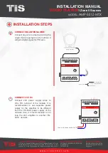
CONNECTING TO AUXILIARY OUT 

Connect RCA lift and right input of 3rd-

party  amplifier  to  module’s  Auxiliary 

output L, R, and GND terminal.

CONNECTING TO 

AUXILIARY 1 AND 2 INPUT 

Connect RCA lift and right output of 3rd-

party player to module’s auxiliary input 1 

or 2 L, R, and GND terminal 

INSTALLATION STEPS  

D-(white-green)&(white-blue)
D+(blue-green)

Cat5e connection

1.5 mm Electric Cable

low voltage cable

low voltage cable

low voltage cable

2.5 mm Electric Cable

low voltage cable

low voltage cable

A/V Cable

D-

D+

AMP5-S1Z-MTX

AUX INPUT 1

GND

R

PRG

AUX INPUT 2

24V DC

DC+ DC-

SPEAKERS

AUX OUT

ANT

L

R GND

L-

L+

R-

R+

L

L

R GND

Cat5

e

POWER

INPUT

GND REM

12+V

SPEAKER OUTPUT

BRIDGED

POWER
PROTECT

FUSE

-

+

LEFT +

- RIGHT

INPUT

Connect To N

Connect To L

AC/DC ADAPTER

Input 220~110V AC

Output  12V DC

SPK

SPK

D-

D+

AUX Cable

D-(white-green)&(white-blue)
D+(blue-green)

Cat5e connection

low voltage cable

low voltage cable

low voltage cable

AMP5-S1Z-MTX

AUX INPUT 1

GND

R

PRG

AUX INPUT 2

24V DC

DC+ DC-

SPEAKERS

AUX OUT

ANT

L

R GND

L-

L+

R-

R+

L

L

R GND

Cat5e

Summary of Contents for X-5S1Z-AMP

Page 1: ...t 2 25 Watt 8 ohms Auxiliary Output Variable Stereo RCA plug output TIS Bus Number of devices on 1 line Max 64 Bus voltage 12 32 V DC Current consumption 15 mA 24 V DC OFF 1 5 A 24V Peak Protection Bu...

Page 2: ...e with four twisted pairs Configure devices in a Daisy Chain Do not cut or terminate live data cables Warranty There is a Two Year warranty provided by law The hologram warranty seal and product seria...

Page 3: ...N rail by two mounting screw holes 2 24D D GND 24D D GND Connect Cat5e TIS network data cable to the TIS BUS port as per the connection diagram No need to loop the TIS bus cable if 2 DIN Rail modules...

Page 4: ...1 AND 2 INPUT Connect RCA lift and right output of 3rd party player to module s auxiliary input 1 or 2 L R and GND terminal INSTALLATION STEPS D white green white blue D blue green Cat5e connection 1...

Page 5: ...ring the single if wire is going to roof or outdoor it will get a better signal for FM radio CONNECT 24V DC Connect 24V power supply wires to DC DC terminal of the module It is recommended to use sepa...

Page 6: ...are subject to change without notice w w w t i s c o n t r o l c o m AUDIO PLAYER 1 Zone 5 Sources Turn on TIS Power Supply The module s PRG LED should start blinking 5 Insert USB or SD card containin...

Page 7: ...change without notice w w w t i s c o n t r o l c o m AUDIO PLAYER 1 Zone 5 Sources To pair the module to the application as a server gateway PAIRING MANUAL PROGRAMMING 1 Long press the PRG buttons f...

Page 8: ...vice Reason 1 TIS BUS connection has a problem check the wires and make sure there s not a short in the connection Reason 2 Manual programming function disabled in the device default is enabled Wall P...

Reviews: