


INSTALLATION MANUAL
MODEL:
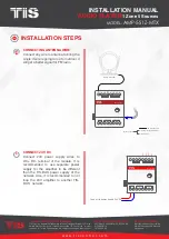
AMP-5S1Z-MTX
TIS CONTROL LIMITED
RM 1502-p9 Easey CommBldg
253-261 Hennessy Rd Wanchai
Hong Kong
TEXAS INTELLIGENT SYSTEM LLC
SUITE# 610. 860 NORTH DOROTHY DR
RICHARDSON
TX 75081.USA
Copyright © 2020 TIS, All Rights Reserved
TIS Logo is a Registered Trademark of Texas Intelligent System LLC in the
United States of America. This company takes TIS Control Ltd. in other
countries. All of the Specifications are subject to change without notice.
w w w . t i s c o n t r o l . c o m
AUDIO PLAYER
1 Zone 5 Sources
Mounting Location
Install in a dry, well-ventilated location.
Controllers may emit some mechanical
noise. Take this into account when deciding
on a mounting location.
Data Cable
Use screened stranded RS485 data cable
with four twisted pairs. Configure devices in
a “Daisy Chain.”
Do not cut or terminate live data cables.
Warranty
There is a Two-Year warranty provided
by law. The hologram warranty seal and
product serial number are available on
each device.
Read Instructions
We recommend that you read this
Instruction Manual before installation.
Safety instructions
Electrical equipment should only be
installed and fitted by electrically skilled
persons.
Failure to observe the instructions may
cause damage to the device and other
hazards.
These instructions are an integral part of
the product and must remain with the end
customer.
Programming
This device can be tested and programmed
manually. Advanced programming
requires knowledge of the TIS Device
Search software and instruction in the TIS
advanced training courses.
Simple Installation
DIN Rail mount facilitates installation.
Fixing points are provided for installation
without the use of DIN rail.


