19
7.
REPLACEMENT OF THE C-POWER LV-UNIT
Remember the Following:
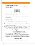
When a C-Power LV-unit becomes empty and must be replaced, the red and green LEDs will blink
simultaneously. Also, the display will indicate that the C-Power LV-unit is empty (refer to figure 21).
Figure 21
When replacing the C-Power LV-unit, the battery set also must be changed. Otherwise, correct
operation cannot be guaranteed. If replacement is done with a C-Power LV-unit of a different size, a
corresponding protection cover must be used.
After installation of the new C-Power LV-unit, the control system continues to operate using the previous
settings for the discharge period.
7.1
Setting the Volume of the C-Power LV-Unit
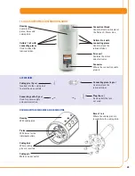
Set the size of the C-Power LV-unit by inserting the contact pin (jumper) into the base plate of the battery
compartment in the drive unit (refer to figure 22). Pointed pliers can be used for plugging in the jumper.
If the position of the jumper does not correspond to the size of the installed C-Power LV-unit, resulting
incorrect signals will lead to malfunctions. (Refer to table 4, chapter 8.2)
To protect the drive unit and the control board from moisture, the exchange must be performed in
dry conditions.
Attention:
If a C-Power LV-unit has been removed from the lubricator and another C-Power LV-unit has been
installed, the control system always assumes that this C-Power LV-unit is new and full.
For this reason,
never use a C-Power LV-unit that is not completely full.
00
% Vol.
Plugged-in jumper for size 250 cc.
Contact pin (jumper)
Figure 22


