background image

Steps

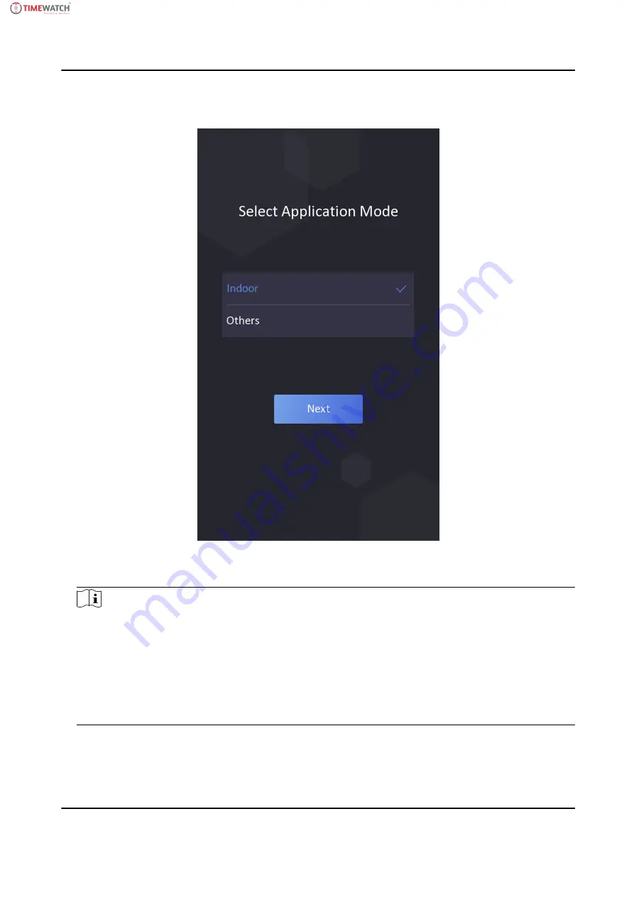
1. On the Welcome page, select Indoor or Others from the drop-down list.

Figure 6-2 Welcome Page

2. Tap OK to save.

Note

• You can also change the settings in System Settings.

• If you install the device indoors near the window or the face recognition function is not

working well, select Others.

• If you do not configure the application mode and tap Next, the system will select Indoor by

default.

• If you activate the device via other tools remotely, the system will select Indoor as the

application mode by default.

24

ULTraFace 671

 Series Face Recognition Terminal User Manual

Summary of Contents for ULtraFace671 Series

Page 1: ...User Manual ULtraFace671 Series Face Recognition Terminal...

Page 2: ...14 4 1 Terminal Description 14 4 2 Wire Normal Device 16 4 3 Wire Secure Door Control Unit 17 Chapter 5 Activation 19 5 1 Activate via Device 19 5 5 3 Activate Device via Client Software 22 Chapter 6...

Page 3: ...via Single Credential 40 6 8 2 Authenticate via Multiple Credential 41 6 9 Basic Settings 41 6 10 Set Biometric Parameters 43 6 11 Set Access Control Parameters 45 6 12 Time and Attendance Status Sett...

Page 4: ...View Device Information 58 7 5 3 Set Time 58 7 5 4 Set DST 59 7 5 5 Upgrade and Maintenance 59 7 5 6 Change Administrator s Password 61 7 5 7 Network Settings 61 7 5 8 Set Video and Audio Parameters...

Page 5: ...n 0 2 s User face recognition accuracy rate 99 Transmits card and user data from or to the client software via TCP IP protocol and saves the data on the client software Imports pictures from the USB f...

Page 6: ...aves the data on the client software Imports pictures from the USB flash drive to the device or export pictures events from the device to the USB flash drive Device management log search and parameter...

Page 7: ...Area Swipe card within this area 3 Display Screen 7 inch LCD touch screen 4 Camera IR Light IR light camera for recording or capturing videos or pictures in IR light 5 Camera White Light White light...

Page 8: ...ug terminal is used for debugging only 13 Power Interface Connect to power supply 14 Wiring Terminals Connect to other external devices including RS 485 card reader Wiegand card reader door lock alarm...

Page 9: ...tallation environment Note For details about installation environment see Tips for Installation Environment 3 2 Install with Gang Box Steps 1 According to the datum line on the mounting template stick...

Page 10: ...ews on the rear panel and remove the sheet to display the wiring terminals 6 Route the cable through the cable hole of the mounting plate and connect to corresponding external devices cables 7 Install...

Page 11: ...e 3 4 Insert Fingerprint Module 10 Align the device with the mounting plate and hang the device on the mounting plate Figure 3 5 Install Device 7 ULTraFace 671 Series Face Recognition Terminal User Ma...

Page 12: ...change it according to your actual needs For easy installation drill holes on mounting surface according to the supplied mounting template 3 3 Install without Gang Box Steps 1 According to the datum l...

Page 13: ...cording to Hole 1 and Hole 2 in the mounting template 3 Insert the screw sockets of the setscrews in the drilled holes Figure 3 8 Insert Screw Socket 4 Align the 6 holes to the mounting plate with the...

Page 14: ...s 6 Route the cable through the cable hole of the mounting plate and connect to corresponding external devices cables 7 Install the sheet back to the device with the two screws 8 Apply Silicone sealan...

Page 15: ...ingerprint module to the holes at the bottom of the main part Figure 3 11 Install Fingerprint Module 10 Align the device with the mounting plate and hang the device on the mounting plate 11 ULTraFace...

Page 16: ...Figure 3 12 Install Device 11 Use two supplied screws SC M4 12TP10 SUS to secure the device and the mounting plate 12 ULTraFace 671 Series Face Recognition Terminal User Manual...

Page 17: ...height here is the recommended height You can change it according to your actual needs For easy installation drill holes on mounting surface according to the supplied mounting template 13 ULTraFace 6...

Page 18: ...troller and the access controller can judge whether to open the door or not Note If cable size is 18 AWG you should use a 12 V power supply And the distance between the power supply and the device sho...

Page 19: ...criptions Group No Function Color Name Description Group A A1 Power Input Red 12 V 12 VDC Power Supply A2 Black GND Ground Group B B1 Alarm Input Yellow Blue IN1 Alarm Input 1 B2 Yellow Black GND Grou...

Page 20: ...ted C7 Orange WG_ERR Wiegand Authentication Failed C8 Purple BUZZER Buzzer Wiring C9 Gray TAMPER Tampering Alarm Wiring Group D D1 Door Lock White Purple NC Lock Wiring NC D2 White Yellow COM Common D...

Page 21: ...he suggested external power supply for door lock is 12 V 1 A The suggested external power supply for the Wiegand card reader is 12 V 1A The suggested power cable s diameter 22 AWG The suggested other...

Page 22: ...or Control Unit Wiring Note The secure door control unit should connect to an external power supply separately The suggested external power supply is 12V 0 5A 18 ULTraFace 671 Series Face Recognition...

Page 23: ...rted The default values of the device are as follows The default IP address 192 0 0 64 The default port No 8000 The default user name admin 5 1 Activate via Device If the device is not activated you c...

Page 24: ...you change your password regularly especially in the high security system changing the password monthly or weekly can better protect your product Proper configuration of all passwords and other secur...

Page 25: ...password in the password field and confirm the password Caution The password strength of the device can be automatically checked We highly recommend you change the password of your own choosing using...

Page 26: ...ivation you can select a language for the device system Figure 6 1 Select System Language By default the system language is English 6 2 Set Application Mode After activating the device you should sele...

Page 27: ...tall the device indoors near the window or the face recognition function is not working well select Others If you do not configure the application mode and tap Next the system will select Indoor by de...

Page 28: ...Before You Start Activate the device and select an application mode Steps Note Tap Skip to skip adding administrator 1 Enter the administrator s name optional and tap Next Figure 6 3 Add Administrator...

Page 29: ...ed The device wired network is connected not connected connecting failed The device Wi Fi is enabled and connected not connected enabled but not connected Shortcut Keys Description Note You can config...

Page 30: ...he administrator can login the device for device operation Steps 1 Long tap on the initial page for 3 s and slide to the left right by following the gesture to enter the admin login page Figure 6 4 Ad...

Page 31: ...can exit the admin login page 6 4 2 Login by Activation Password You should login the system before other device operations If you do not configure an administrator you should follow the instructions...

Page 32: ...e The device will be locked for 30 minutes after 5 failed password attempts Figure 6 6 Home Page 6 5 Communication Settings You can set the network parameters the Wi Fi parameter and the RS 485 parame...

Page 33: ...red Network Settings 3 Set DHCP IP Address Subnet Mask or Gateway Note The device s IP address and the computer IP address should be in the same IP segment 6 5 2 Set Wi Fi Parameters You can enable th...

Page 34: ...Only digits letters and special characters are allowed in the password 5 Set the Wi Fi s parameters By default DHCP is enable The system will allocate the IP address the subnet mask and the gateway au...

Page 35: ...If you select Access Controller If connect the device to a terminal via the RS 485 interface set the RS 485 address as 2 If you connect the device to a controller set the RS 485 address according to t...

Page 36: ...nagement On the user management interface you can add edit delete and search the user 6 6 1 Add Face Picture Add user s face picture to the device And the user can use the face picture to authenticate...

Page 37: ...picture adding page Figure 6 11 Add Face Picture 6 Look at the camera Note Make sure your face picture is in the face picture outline when adding the face picture Make sure the captured face picture...

Page 38: ...ngerprint Steps Note The function should be supported by the device 1 Long tap on the initial page for 3 s and slide to the left right by following the gesture and enter the device backend 2 Tap User...

Page 39: ...added card Steps 1 Long tap on the initial page for 3 s and slide to the left right by following the gesture and log in the backend 2 Tap User to enter the Add User page 3 Connect an external card rea...

Page 40: ...page for 3 s and slide to the left right by following the gesture and log in the backend 2 Tap User to enter the Add User page 3 Tap the Employee ID field and edit the employee ID Note The employee I...

Page 41: ...tion Mode 3 Select Device or Custom as the authentication mode Device If you want to select device mode you should set the terminal authentication mode in Access Control Settings page first For detail...

Page 42: ...sh drive format is FAT32 The imported pictures should be saved in the root directory enroll_pic and the picture file s name should be follow the rule below Card No _Name_Department_Employee ID_Gender...

Page 43: ...gured authentication mode You can authenticate identity via 1 1 matching or 1 N matching 1 N Matching Compare the captured face picture or the collected fingerprint picture with all face pictures or a...

Page 44: ...can be normal IC card or encrypted card If the QR Code Scanning function is enabled you can put the QR code in front of the device camera to authenticate via QR code 2 After the previous credential i...

Page 45: ...pecified Room No Call Room When you tap the call button on the authentication page you should dial a room No to call Call Center When you tap the call button on the authentication page you can call th...

Page 46: ...et the device installed building No Unit No Set the device installed unit No 6 10 Set Biometric Parameters You can customize the face parameters to improve the face recognition performance The configu...

Page 47: ...hen performing live face authentication Note Biometric recognition products are not 100 applicable to anti spoofing environments If you require a higher security level use multiple authentication mode...

Page 48: ...rk environment And you can set he ECO mode threshold ECO mode 1 N and ECO mode 1 1 ECO Threshold When enabling the ECO mode you can set the ECO mode s threshold The larger the value the easier the dev...

Page 49: ...t module supports the fingerprint related function Biometric recognition products are not 100 applicable to anti spoofing environments If you require a higher security level use multiple authenticatio...

Page 50: ...h time and attendance function on the client software 6 12 1 Disable Attendance Mode via Device Disable the attendance mode and the system will not display the attendance status on the initial page Ta...

Page 51: ...be marked as a valid attendance 6 12 3 Set Auto Attendance via Device Set the attendance mode as auto and you can set the attendance status and its available schedule The system will automatically ch...

Page 52: ...time 5 Tap Confirm 6 Repeat step 1 to 5 according to your actual needs Note The attendance status will be valid within the configured schedule Result When you authenticate on the initial page the aut...

Page 53: ...to enter the T A Status page 2 Set the Attendance Mode as Manual and Auto Figure 6 18 Manual and Auto Mode 3 Select an attendance status and set its schedule 1 Select Check In Check Out Break Out Brea...

Page 54: ...stem Maintenance You can view the system information and the capacity You can also upgrade the device restore to factory settings and restore to default settings Long tap on the initial page for 3 s a...

Page 55: ...evice from the client software call the master station from the device call the client software from the device or call the indoor station from the device 6 14 1 Call Client Software from Device Steps...

Page 56: ...guration page Note For details about the operation see the user manual of the master station 6 Call the center If you have configured to call center in the Basic Settings you can tap to call the cente...

Page 57: ...rol panel of the software pops up 3 Click Device Management to enter the Device Management interface 4 Add the indoor station and the device to the client software Note For details about adding device...

Page 58: ...in page Enter the device user name and the password Click Login Login via Remote Configuration of Client Software Download and open the client software After adding the device click to enter the live...

Page 59: ...sub stream Select the window division type when starting live view Full screen view 7 3 Person Management Click and add the person s information including the basic information card authentication mo...

Page 60: ...cture format should be JPEG and the size should be less than 200K Click Save to save the settings Add Authentication Mode Click User Add to enter the Add Person page Set the authentication mode Click...

Page 61: ...computer and click Save You can also click Open to open the file folder to view details Set Captured Pictures Saving Path Click Configuration Local to enter the Local page Select a saving path from y...

Page 62: ...e manually or check Sync with Computer Time to synchronize the device time with the computer s time 7 5 4 Set DST Steps 1 Click Configuration System System Settings DST Figure 7 4 DST Page 2 Check Ena...

Page 63: ...tion Import and Export Parameters Click Configuration System Maintenance Upgrade Maintenance Export Click Export to export the logs or device parameters Note You can import the exported device paramet...

Page 64: ...mbers and special characters in order to increase the security of your product And we recommend you change your password regularly especially in the high security system changing the password monthly...

Page 65: ...Server Set the preferred DNS server and the Alternate DNS server according to your actual need Set EHome Parameters Set the EHome parameters for accessing device via EHome protocol Steps Note The fun...

Page 66: ...name password and encryption type Click Connect When the Wi Fi is connected click OK 4 Optional Set the WLAN parameters 1 Click TCP IP Settings 2 Set the IP address subnet mask and default gateway Or...

Page 67: ...tings after the configuration 7 5 9 Set Video Intercom Parameters The device can be used as a door station or outer door station You should set the device No before usage Set Device No Click Configura...

Page 68: ...address After setting the parameters you can communicate among the access control device door station indoor station master station and the platform Click Save to save the settings after the configur...

Page 69: ...to your actual needs from the drop down list Display Result with Check Face Picture Name or Employee ID When authentication is completed the system will display the selected contents in the result Mi...

Page 70: ...ccording to the door No Baud Rate The baud rate when the devices are communicating via the RS 485 protocol Output Type If you select Access Controller as the peripheral type you should set the paramet...

Page 71: ...ss contrast saturation and sharpness Steps 1 Click Configuration Image Figure 7 14 Image Settings Page 2 Configure the parameters to adjust the image Video Standard Set the video frame rate when perfo...

Page 72: ...ure the image 7 5 14 Set Supplement Light Brightness Set the device supplement light brightness Steps 1 Click Configuration Image Figure 7 15 Supplement Light Settings Page 2 Click SUPPL Light Supplem...

Page 73: ...rity level use multiple authentication modes Live Face Detection Security Level After enabling the face anti spoofing function you can set the matching security level when performing live face authent...

Page 74: ...de when no operation with the configured sleep time Customize Screen Saver Enable the function and you can upload the screen saver pictures from the local PC You can also set the slide show interval f...

Page 75: ...the picture below Do not wear hat sunglasses or other accessories that can affect the facial recognition function Do not make your hair cover your eyes ears etc and heavy makeup is not allowed Postur...

Page 76: ...158 ULTraFace 671 Series Face Recognition Terminal User Manual...

Page 77: ...Value Candle 10Lux Bulb 100 850Lux Sunlight More than 1200Lux 2 Install the device at least 2 meters away from the light and at least 3 meters away from the window or door 3 Avoid backlight direct an...

Page 78: ...Figure D 2 Device without Fingerprint Module ULTraFace 671 Series Face Recognition Terminal User Manual 75...

Page 79: ......

Reviews: