Tiger Optics HALO M7000 Series Instruction Manual Download Page 52

HALO Users Manual


 Revision G 


44

7.3  Troubleshooting Guide 

Table 7-1 contains a troubleshooting guide of the most common problems associated with the 
unit’s operation. System Fault alarms are included in the Table. If none of these step helps to 
resolve the problem, contact trained Tiger Optics service personnel immediately. 

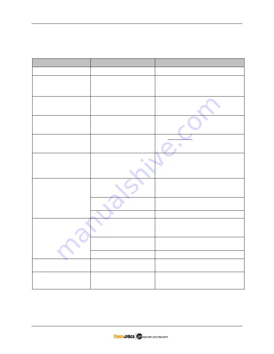
Table 7-1    Troubleshooting 

Circumstance 

Probable Cause 

Corrective Action 

No display 

Unit not powered up 

Check fuse and plug. 

Reading higher than 
expected 

Dead-legs, leaks, or 
moisture traps in the 
sampling system 

Follow the “Preparing the Sample 
Line” and “Leak Check” procedures. 

Slow response time 

Dead-legs, leaks, or 
moisture traps in the 
sampling system 

Follow the “Preparing the Sample 
Line” and “Leak Check” procedures. 

Reading continues to 
decrease 

Reading not yet stable 

Purge with dry gas then reapply the 
sample. Repeat as often as required 
until the reading stabilizes. 

Not reading correct 
concentration of a span 
gas 

Incorrect gas type chosen.  See 

Section 4.2


Reading is erratic  


Contaminated optics 

Consult with factory. 

Fine air leaks in sample 
line 

Leak test the sample line and 
connections following the procedure in 
Table 3-3. 

Fine air leaks in sample 
cavity  

Leak test following the procedure in 
Table 3-3. 

Reading is noisy 

Optics need re-alignment 

Consult with factory. 

Above the maximum ring-
down value, too much 
water. 

Stop and purge the unit with a dry gas 
until on scale. 

Optical bench out of 
alignment 

Consult with factory. 

Ring-down Alarm 

Detector failure 

Consult with factory. 

Ring-down Fault and 
Laser Current Fault 

Laser is not operating 

Check that there is current. If not, 
consult factory. 

Ring-down Fault and  
Laser Temperature 
Fault 

Temperature controller has 
failed 

Consult with factory. 

Summary of Contents for HALO M7000 Series

Page 1: ...HALO Trace Gas Analyzer Instruction Manual M7000 Series Rev G ...

Page 2: ... pledge to our customers is to continue to keep pace with market needs now and long into the future Finally thank you for choosing a Tiger Optics HALO Trace Gas Analyzer Please remember that we value your opinion as much as your patronage We welcome your comments questions and suggestions about our equipment Sincerely The Tiger Optics Staff 2006 Tiger Optics LLC All rights reserved No part of this...

Page 3: ...returned without an RA number may be sent back at customer expense Units manufactured seven 7 years prior or older may not be repairable based on available components Please contact the Tiger Optics Service Department prior to returning the unit Items considered expendable such as fuses are not under warranty This warranty shall not apply to equipment and parts repaired or altered outside of Tiger...

Page 4: ...se which may create explosive mixtures like hydrogen and oxygen requires complete purging with an inert gas Failure to remove all gas residue by not purging with an inert gas will expose you to risk of injury or explosion Use only an approved detachable power cord 1 meter 120V or 220V 2 pole 3 wire ground 15 amp power cord Disconnect the analyzer from AC power source before performing any maintena...

Page 5: ...ng of a Single HALO Unit 9 2 4 Front Panel of HALO Unit 10 2 5 Rear Panel of HALO Unit 11 3 Installing Your HALO 12 3 1 Overview 12 3 2 Unpacking Your HALO 12 3 3 Serial Number Identification 14 3 4 Preparing the Sample Line 15 3 5 Assembling the Sample Line 16 3 6 Leak Testing the Sample Line 17 3 7 HALO Location 18 3 8 Pressure and Venting Considerations 19 3 9 Connection Considerations 20 3 10 ...

Page 6: ...ar Functions 31 4 5 Ringdown Alarm 32 5 Data Capture Guide 33 5 1 Setting up the Connection 33 5 2 Saving Data to a Text File 35 5 3 Deleting Data from HALO Memory 35 6 Remote Operations 36 6 1 Overview 36 6 2 Interfacing 36 6 3 Commands 37 7 Troubleshooting and Maintenance 43 7 1 General Information 43 7 2 Preventive Maintenance 43 7 3 Troubleshooting Guide 44 7 4 Return a Unit for Repair 45 8 Sp...

Page 7: ...5 Connecting to the Sample Inlet and Outlet 21 Table 3 6 Capping the Sample Inlet and Outlet 23 Table 6 1 RS 232 DB 9F Pin Designation 36 Table 6 2 Host to HALO Connections 36 Table 7 1 Troubleshooting 44 List of Figures Figure 1 2 Ringdown Time 2 Figure 1 3 Absorption Spectrum 2 Figure 1 4 Concentration N Calculation 3 Figure 2 1 HALO Two Unit Dimension Drawing 8 Figure 2 2 HALO Single Unit Dimen...

Page 8: ...re 4 3 Gas Type Setup Tab of the Settings Window 26 Figure 4 4 Output and Communications Tab of the Settings Window 27 Figure 4 7 Operating Mode Select Window 30 Figure 4 8 Trend Graph 31 Figure 4 9 Ringdown Signal 32 Figure 5 1 Connection Setup Windows 33 Figure 5 2 Port Settings HALO Properties and ASCII Setup 34 Figure 5 3 Connection Test 34 Figure 5 4 Capture Text 35 ...

Page 9: ...ser emits a directed beam of light energy through an ultra high reflective mirror into the absorption cell cavity Figure 1 1 Cavity Ringdown Spectroscopy The light reflects back and forth between two ultra high reflective mirrors multiple times On each successive pass a small amount of light or ringdown signal emits through the second mirror and is sensed by the light detector Once the photodiode ...

Page 10: ...alue equivalent to a zero baseline Figure 1 3 Figure 1 3 Absorption Spectrum The concentration of the sample species is calculated Figure 1 4 by comparing this tau zero value to the tau measured ringdown time These calculations are based on first principles and follow the Beer Lambert Law 0 10 20 30 40 50 60 70 80 90 100 1391 3 1391 8 1392 3 1392 8 Wavelength nm sec zero peak ...

Page 11: ... 3 1 R c d zero 1 Nd R c d 1 1 1 zero c N c Speed of Light Absorption Cross Section d Cell Length Ringdown Time R Reflectivity of the Mirror Laser Frequency N Molecular Density concentration Figure 1 4 Concentration N Calculation ...

Page 12: ...nmental Conditions 10º 40ºC 30 to 80 R H Non condensing Storage Temperature 10 C to 50 C Technology Method Cavity Ring Down Spectroscopy CRDS Laser Light Source Continuous Wave CW Near IR diode laser Approvals CE Marked LVD and EMC approved Patents U S Patent 5 528 040 U S Patents Pending Gas Sample Conditions Sample Inlet Pressure 10 125 psig 1 7 9 6 bara Sample Outlet Pressure 2 0 psig back pres...

Page 13: ... User programmable alarm set points Output Signals Recorder Alarm Isolated 4 20 mA output 2 Form C relay user configurable 1 Form C relay for system fault monitoring Laser status ringdown status 802 11g Wireless optional User Interface 5 6 Color LCD display with touch screen 10BaseT Ethernet RS 232 can be changed to RS 422 Mounting and Hook up Considerations Configuration 2 Units per 19 relay rack...

Page 14: ...on condensing Storage Temperature 10 C to 50 C Technology Method Cavity Ring Down Spectroscopy CRDS Laser Light Source Continuous Wave CW Near IR diode laser Approvals CE Marked LVD and EMC approved Patents U S Patent 5 528 040 U S Patents Pending Gas Sample Conditions Sample Inlet Pressure 30 125 psig 3 1 9 6 bara Sample Outlet Pressure 2 0 psig back pressure or vacuum Flow Rate 0 5 to 1 8 slpm d...

Page 15: ... User programmable alarm set points Output Signals Recorder Alarm Isolated 4 20 mA output 2 Form C relay user configurable 1 Form C relay for system fault monitoring Laser status ringdown status 802 11g Wireless optional User Interface 5 6 Color LCD display with touch screen 10BaseT Ethernet RS 232 can be changed to RS 422 Mounting and Hook up Considerations Configuration 2 Units per 19 relay rack...

Page 16: ...ers Manual Revision G 8 2 2 Dimension Drawing The HALO dimensions of the front rear and side views are shown in Figure 2 1 Two analyzers will fit into a 19 relay rack Figure 2 1 HALO Two Unit Dimension Drawing ...

Page 17: ...HALO Users Manual Revision G 9 2 3 Dimension Drawing of a Single HALO Unit Figure 2 2 HALO Single Unit Dimension Drawing ...

Page 18: ...HALO Users Manual Revision G 10 2 4 Front Panel of HALO Unit Figure 2 3 HALO Two Unit Front Panel Color LCD Display and Touch Screen Power Switch ...

Page 19: ...HALO Users Manual Revision G 11 2 5 Rear Panel of HALO Unit Figure 2 4 HALO Two Unit Rear Panel Sample Inlet Sample Outlet RS 232 Connection I O Connection Power Connection Ethernet Connection ...

Page 20: ...acking slip to ensure the shipment is complete Each HALO will include separately at least the following items Power cord Certificate of calibration Quick Start Guide RS 232 USB converter cable Any missing items should be reported to Tiger Optics immediately 4 The HALO is shipped ready for use To keep the Ring Down Cavity dry and clean during shipping the gas inlet and outlet connections are capped...

Page 21: ...alyzer to another location or back to the factory ATTENTION Save Quick Start Guide Save the Quick Start Guide in a ready file in case the unit needs to be capped off or moved to a different location ATTENTION Save Certificate Save the certificate of safe operating condition This must be completed and returned with any unit returned to Tiger Optics ...

Page 22: ...LO analyzer has a serial number plate on the rear of the unit If you call for technical assistance please be ready to provide this number The identifying features of the number are XXXXX XX X Serial Code Product Code Hardware Revision Figure 3 1 Serial Number Identification ...

Page 23: ...race gas impurities have been allowed to contaminate the sample line additional purging is required This section provides instructions for assembling and leak testing the sample line Precautions to be taken to measure moisture accurately Measuring moisture is challenging since minute air leaks can cause erroneous high readings especially at low PPB concentrations The following precautions are to b...

Page 24: ... prevent against contamination of the unit 2 When finished with purge cap the sample line with a new gasket and VCR fitting ATTENTION Make sure the sample line and fittings are free of grease and fine particulates Do not use copper plastic or bellows style flexible tubing ATTENTION The recommended tubing connection to the analyzer is 316L electropolished stainless steel The sample line tubing diam...

Page 25: ...d fittings with a helium leak detector from the sample source to the analyzer fittings ATTENTION Do not put Snoop on fittings to be helium leak tested since it can cause high erroneous readings A helium leak detector such as a portable thermoconductivity detector TCD or quadrupole mass spectrometer is recommended Watch for drafts since they also cause high or off scale readings while using the hel...

Page 26: ...LO is intended to be rack mounted but can also be mounted on a cart or set on a sturdy flat surface 2 Make sure the power switch on the front panel is off and connect the power cord to a suitable power source 3 Connect the mA outputs and alarm relay contacts to SCADA DAQ or PLC if so desired Figure 3 2 Alarm Relay and mA Output Connector ...

Page 27: ... To avoid backpressure from restricted flow the vent line must consist of tubing The vent line must end in an area with no greater than atmospheric pressure Care should be taken to insure that the back pressure at the sample outlet never goes above 2 psig 1 15 bara If it is possible that the vent line could become pressurized a low cracking pressure check valve should be employed to prevent back f...

Page 28: ...e and does not require an exact cell pressure The pressure is set at the factory and requires no field adjustment After the sample gas passes through the sample cell it flows through an orifice and out the sample outlet fitting The Cavity Ring Down method does not require an exact sample flow rate However the propagation of moisture is flow dependent Higher flow rates will provide faster speed of ...

Page 29: ...ged sample line to the sample inlet 2 With a positive flow from an inert gas source uncap the sample outlet and with a new VCR gasket immediately connect the Vent line to the sample outlet If the Vent line is connected to a vacuum pump the pump line should now be opened ATTENTION Save both Caps for future use When Unit is not in use it must be purging or be properly capped Sect 2 10 ATTENTION Ensu...

Page 30: ...r Optics logo then the Main Display screen 2 Press the Mode button on the Main Display in the upper left corner 3 Choose Measure Mode from the list of modes The HALO s laser will stabilize center and begin taking contaminant readings 4 When the HALO begins to display a value near the expected concentration of contaminant press the Mode button again 5 Choose Tune from the list of modes The HALO wil...

Page 31: ... 7 Capping the Sample Inlet and Outlet Step Action 1 If the Vent line is connected to a vacuum pump ensure pump line is closed With a positive flow from an inert gas source disconnect the Vent line and with a new VCR gasket immediately connect the VCR sample outlet cap 2 With a positive flow from the inert gas source disconnect the Sample Inlet line and with a new VCR gasket immediately connect th...

Page 32: ...e screen the user is touching This pressure sensitive technology provides high resolution selectivity for accurate pointing Simply touch the screen where you would normally click with a mouse You can use your finger or a stylus like an unopened pen A Virtual Keypad is built into the HALO operating software for use when numerical input is required Clicking on a numerical input box will bring up the...

Page 33: ...tion Service Tune or Measure The Laser status indicates the status of the laser source The display will show either OK or ALARM The Ringdown status indicates the status of the ringdown acquisition The display will show either OK or ALARM The Alarm Status areas indicated if the current value exceeds the user selectable alarm points The display will show either OK or ALARM The Status bar indicates t...

Page 34: ... bring up the Settings window press on the Settings button on the toolbar of the main display The Settings window is made up of four tabs The four tabs are Gas Type Outputs Communication Data Logging and Manual Settings The Gas Type settings tab allows selection of the proper sample gas by pressing the appropriate gas type After selecting the proper gas you can select another tab on the settings w...

Page 35: ... when the measured concentration exceeds the value specified by the user When one of these alarms is in effect the Alarm 1 or Alarm 2 text on the Alarm Status area of the Main Display will turn red and show the text AL instead of OK The Use DHCP and Ethernet fields are used to configure the unit s IP addresses The user may select any of the displayed baud rates by selecting the appropriate radio b...

Page 36: ... The next time an acceptable concentration is reached the Tune will perform automatically We recommend running a Tune every month to ensure the precision of your HALO A Laser Optimization resets the Laser Current to 95 mA then adjusts the Laser Temperature to verify and if necessary reset the temperature so that the laser s wavelength matches the contaminant e g moisture absorption peak A Laser Op...

Page 37: ...t unless instructed to do so by a Tiger Optics Service Representative The areas that can be controlled are Laser Current Laser Temperature Trigger Level and 4 20 mA Output Fields with a gray background are read only and indicate the value of specific system parameters The date and time are set using the mm dd yy format for the date and hh mm ss format for the time The time is stored and displayed ...

Page 38: ... the instrument During shipment of the unit it is possible that shock and vibration may have caused slight changes in the alignment of the cavity Running a Tune Cycle will automatically compensate for any such changes We recommend running a Tune Cycle to ensure precision of your measurements 1 Upon installation 2 Whenever the sample gas is changed 3 Once per month even if the gas type does not cha...

Page 39: ...he system free of contaminants that may degrade the system or cause excessive dry down times 4 4 Other Toolbar Functions Trend Graph To bring up the Trend window press on the Trend button on the toolbar of the main display Figure 4 8 Trend Graph The Trend graph will display a graph of measurement results for the date entered in the date box One day at a time will be displayed To change the scale o...

Page 40: ...oo high when there is a system contamination or in rare cases when the alignment of the laser is off or the detector has failed When a Ringdown Alarm is in effect the concentration are will flash red and read OVER Additionally the Ringdown text in the Alarm Status area will turn red and instead of OK it will read AL The data points logged during a Ringdown Alarm on the Trend graph will appear red ...

Page 41: ...now open type a name for the New Connection Fig 5 1a then press Ok Figure 5 1 Connection Setup Windows 3 Port Selection a Under the Connect Using pull down menu choose the COM port for the serial or USB port that is being used for communication with the HALO Fig 5 1b b If you do not know the COM port then select the lowest COM port number c Press Ok 4 Port Settings a From the main screen on your H...

Page 42: ... e HyperTerminal is now configured to communicate with your HALO Commands are listed in the User s Manual 6 Test the Connection a Type Opmode 0 then press Enter using HyperTerminal b A 0 should be returned and the HALO should be in service mode as in Fig 5 3 If you were not able to type or the HyperTerminal did not respond to the commands repeat the procedure with another COM port c Press File Sav...

Page 43: ... Press Browse to choose a location and name for your file c Select Start d Type the command DTD into your HyperTerminal interface e Data should now download to HyperTerminal and into the text file specified in part a Figure 5 4 Capture Text 5 3 Deleting Data from HALO Memory 1 Deletion Commands a Type the command Fact 1 b Select enter c Type Erase_Trend_Data d Select Enter ...

Page 44: ...9600 n 8 1 baud and bit rate setting but may be set to different baud rates The host PC must be configured for a matching baud rate no parity 8 data bits and 1 stop bit RS 232 CONNECTOR The HALO RS232 interface is located on the rear panel It is a 9 pin male DB connector configured as a DTE device Data is transmitted out of HALO using pin 3 and is received on pin 2 This allows a one to one DB 9M t...

Page 45: ...el passcode for local user interface unlocking TAUEMPTY Read the off peak ringdown time i e Tau Zero TAUESTD Read the standard deviation in the off peak ringdown time TAU Read the on peak ringdown time TAUSTD Read the standard deviation of the on peak ringdown time TIME Read the current time and date set on the HALO ERROR MESSAGES The HALO always replies to a command If the command is incorrect or...

Page 46: ...10 23 07 14 49 10 5332 36 CONC Purpose Read the calculated concentration Syntax CONC Arguments none Remarks The CONC command returns the last successful reading in ppb Example Command CONC Reply 1 23 FILTER Purpose Read or set the data smoothing filter Syntax FILTER FILTER n Arguments n the filter setting 10 through 1000 Remarks The FILTER command is used to set or read the data filtering Valid se...

Page 47: ... status A value of zero unlocks the front panel A value of 1 locks the front panel Example Command LOCK 1 Reply 1 Sets the front panel lock status to true A password will be required to access the instrument through the touch screen Errors BAD RANGE The value n is invalid OPMODE Purpose Read or set the operating mode Syntax OPMODE OPMODE n Arguments n the operating mode 0 3 Remarks The OPMODE comm...

Page 48: ...assword Syntax PASSCODE PASSCODE s Arguments t the string for the password up to 4 numeric characters Remarks The PASSCODE command reads or sets the password required by the user when trying to access a locked HALO Use only numeric characters 0 9 to ensure the unit can be unlocked from the touch screen Example Command PASSCODE 1966 Reply 1966 Sets the password to 1966 Errors none TAU Purpose Read ...

Page 49: ...AUEMPTY Purpose Read the off peak ringdown time Syntax TAUEMPTY TAUEMPTY Remarks The off peak ringdown time is normally calculated by the HALO s TUNE mode Example Command TAUEMPTY Reply 72 123 Errors none TAUESTD Purpose Read the standard deviation in the off peak ringdown time Syntax TAUESTD Arguments f the standard deviation of the ringdown time in microseconds Remarks The standard deviation in ...

Page 50: ...HALO Users Manual Revision G 42 TIME Purpose Read the set time and date on the HALO Syntax TIME Remarks Example Command TIME Reply 06 13 2008 15 35 45 Errors none ...

Page 51: ...Optimization Over time the laser may drift off the contaminant s absorption peak An Optimization scan is recommended every 12 months or whenever the current drops below 85 00 mA to ensure the unit is operating optimally An Optimization Scan about 10 15 minutes long will verify the laser is on peak and adjust the temperature to return it to the precise wavelength if needed Refer to Section 4 2 for ...

Page 52: ... decrease Reading not yet stable Purge with dry gas then reapply the sample Repeat as often as required until the reading stabilizes Not reading correct concentration of a span gas Incorrect gas type chosen See Section 4 2 Reading is erratic Contaminated optics Consult with factory Fine air leaks in sample line Leak test the sample line and connections following the procedure in Table 3 3 Fine air...

Page 53: ...ay cause damage to your flow system and will void the warranty on your unit Package the unit in the original shipping box for proper protection If proper packaging is not used you will be charged for an appropriate box for your unit s return Ensure you have enclosed paperwork with your company name contact person phone and fax numbers 4 Send to our factory address Tiger Optics LLC 250 Titus Avenue...

Page 54: ... proforma invoice Note To reduce unnecessary inbound expense be sure to instruct your subcontracted USA freight forwarder to send the shipment Gratis to our Customs Broker and not to send it on a collect basis Additionally the return invoice must include a list of the contents Tiger Optics Return Authorization Number RA declared value and a statement as follows USA goods being returned to manufact...

Page 55: ...een tested to determine the effects of collisional broadening Selecting the proper gas from the menu is important to making accurate measurements so that the proper broadening factor is applied The following gases have been studied to determine the feasibility of H2O measurements Nitrogen N2 Nitrogen is a homo nuclear diatomic molecule that has no measurable absorption in the near infrared NIR The...

Page 56: ...HBr to be done at a different wavelength The water absorption peaks are significantly widened in HBr This reduces the sensitivity of H2O measurements vs N2 HBr is extremely hygroscopic As HBr propagates through a flow system it absorbs any water in the flow system it comes in contact with This effect causes significant settling times when making measurements in HBr When switching between an inert ...

Page 57: ...Instruction Manual M7000 Series ...

Reviews: