


Using a Remote Unit
01-0868-401B 12/02
35
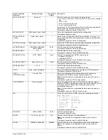
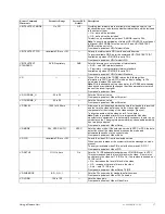
QD SET <
paramters
>
where <
parameters
> =
qd set lnb rf lo cr dr
—
The QD SET command enables you to enter the LNB, RF, LO, CR and
DR parameters using one command string:
■
LNB – Sets the low noise block (LNB) voltage of the demodulator.
Parameter range:
■
Off – sets voltage to zero; no power to LNB
■
13V – sets the LNB voltage to 13 V (horizontal polarization)
■
18V – sets the LNB voltage to 18 V (vertical polarization)
Note: The TDR60 supplies the LNB power at 13V DC or 18 V DC,
which allows an LNB downconverter to set the receive signal
polarization to either horizontal or vertical. If you do not need the
TDR60 to supply the LNB power, set to Off.
■
RF – Sets the demodulator to the frequency of the incoming RF
signal. Acceptable ranges are 950 to 2150 MHz above or below the
local oscillator frequency.
Parameter range: 2000 to 15000 MHz
■
LO – Sets the frequency of the demodulator to match your LNB
downconverter local oscillator frequency.
Parameter range: 2000 to 15000 MHz
■
CR – Sets the Viterbi code rate of the demodulator.
Parameter range: 1/2, 2/3, 3/4, 5/6, 7/8
■
DR – Sets the data rate of the transport data stream of the
demodulator.
Parameter range: 1000000 to 60000000
For example: qd set 13v 12174 10000 3/4 5500000
where
■
13V = LNB setting
■
12174 = RF setting
■
10000 = LO setting
■
3/4 = CR setting
■
DR = DR setting
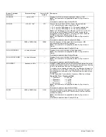
QD SR
2000000 to 30000000 Sps
5500187 Sps
Sets the demodulator to the frequency of the incoming RF signal.
Acceptable ranges are 950 to 2150 MHz above or below the local
oscillator frequency.
Note
: This command is only applicable when Inp Type is set to
Demod.
Front panel equivalent: Input>Config>Symbol Rate
RE
—
—
Reloads all programmable logic and firmware, and restarts the system.
All configuration parameters return to the last saved settings stored in
non-volatile (flash) memory.
Note
: The TDR60 clears the fault history log whenever you reset the
unit. If you are experiencing problems and decide to reset the unit, first
issue the FH command and write down all faults contained in the fault
history log. You may need to use the list of faults as a troubleshooting
aid.
Front panel equivalent: Control>Reset
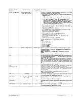
UD
x
where
x
= A or B
—
—
When UD
A
is entered, the TDR60 returns the following
synchronous
user data information: PID, settings, and data rate settings.
When UD
B
is entered, the TDR60 returns the following
asynchronous
user data information: PID, settings, baud rate, data bits, parity, and
stop bit settings.
Note
: Only one user data channel may be active at a time.
Front panel equivalent: None
UDA DR
0 - 2048000
0
Queries the clock rate for the synchronous (channel A) user data port.
Front panel equivalent: Data>Synch>Data Rate
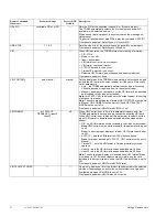
UDV BAUD
110, 300, 600, 1200, 2400,
4800, 9600
9600
Sets the baud rate for the specified asynchronous (channel B) user
data port.
Front panel equivalent: Data>Asynch>Baud
UDB DATA
7, 8
8
Sets the data bits for the specified asynchronous (channel B) user data
port.
Front panel equivalent: Data>Asynch>Data Bits
UDB PARITY
None, Odd, Even
None
Sets the parity for the asynchronous (channel B) user data port.
Front panel equivalent: Data>Asynch>Parity
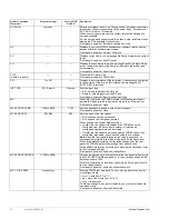
Remote Command
Mnemonic
Parameter Range
Factory DVB
Default
Description


