


34
HA0143T Rev 12K Sept 2015
Chapter 5
5.6.3 Electrical Connections and Software Settings - Off Hub (Hard Wired)
Operation
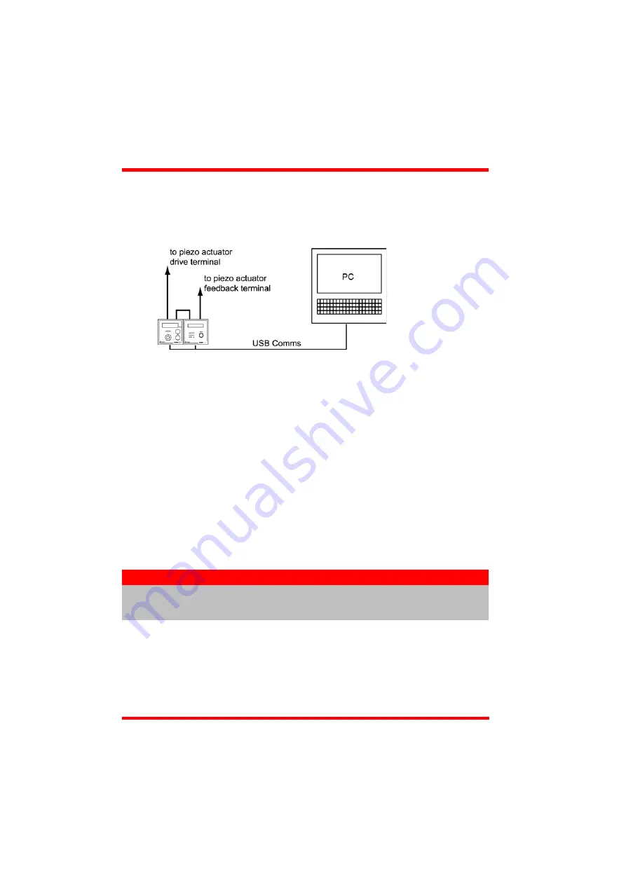
The following procedure describes a typical set up, when a TPZ001 piezo driver cube
and a TSG001 Strain Gauge Reader are used to control a piezo actuated stage - see
Fig. 5.12 for a general system schematic diagram..
Fig. 5.12 Typical System Set Up - Off Hub (Hard Wired) Operation
1) Perform the mechanical installation as detailed in Section 3.2. of this manual and
also in the manual supplied with the T-Cube Strain Gauge Reader.
2) Connect the MONITOR terminal on the rear panel of the strain gauge unit to the
EXT IN terminal on the rear panel of the piezo unit.
3) Connect the STRAIN GAUGE I/P terminal on the rear panel of the strain gauge
unit to the Feedback connector on the piezo actuator.
4) Connect the HV OUT terminal on the rear of the Piezo driver to the associated
piezo actuator.
5) Connect the units to their power supplies - see Section 3.3.5. of this manual and
also the manual supplied with the Strain Gauge Readers.
6) Connect the PSU to the main supply and switch ‘ON’. The version number of the
embedded software is displayed on the Piezo unit during boot up. The software
version is useful when requesting technical support.
7) Connect each controller unit to your PC.
8) Windows
TM
should detect the new hardware. Wait while Windows
TM
installs the
drivers for the new hardware.
9) Run the Kinesis software - Start/All Programs/Thorlabs/Kinesis/Kinesis.
Note
The USB cable should be no more than 3 metres in length.
Communication lengths in excess of 3 metres can be achieved by using
a powered USB hub).
Summary of Contents for TPZ001
Page 1: ...TPZ001 Piezo Driver User Guide Original Instructions...
Page 56: ...Appendix E 56 HA0143T Rev 12K Sept 2015 E 3 CE Certificate...
Page 57: ...57 T Cube Piezo Driver...
Page 58: ...58...
Page 60: ...60 www thorlabs com...


