


29
T-Cube Piezo Driver
The T-Cube positions on the hub and associated parameter settings described are by
no means the only possible options. For further information, see Section 5.6.2..
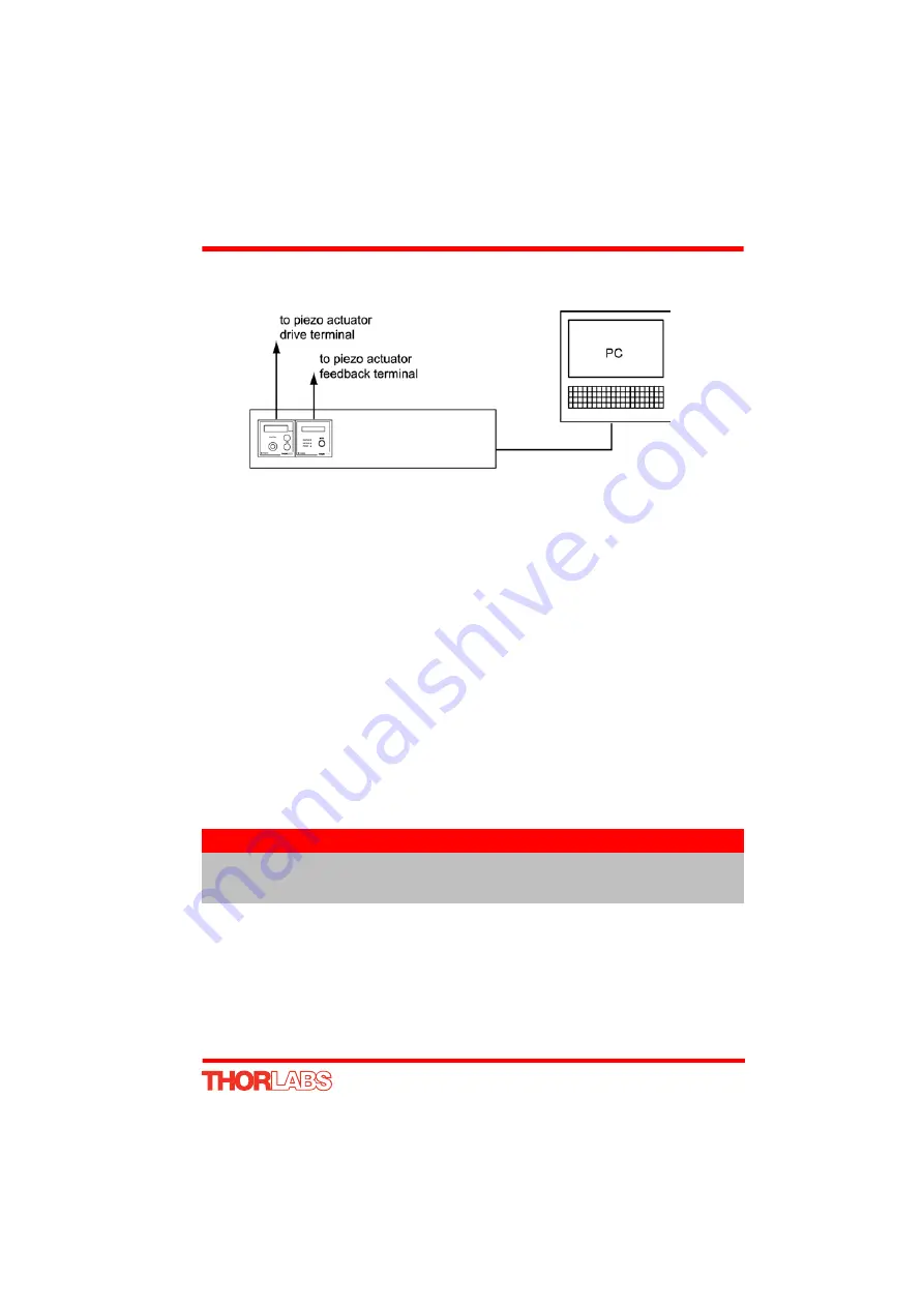
Fig. 5.7 Typical System Set Up - Hub Operation
1) Perform the mechanical installation as detailed in Section 3.2. of this manual and
also in the manual supplied with the T-Cube Strain Gauge Reader.
2) Install the T-Cube units onto the controller hub. Fit the Piezo unit in bay 1, and the
Strain Gauge Reader in bays 2 as shown in Fig. 5.7.
3) Connect the HV OUT terminal on the rear of the Piezo driver to the associated
piezo actuator.
4) Connect the STRAIN GAUGE I/P terminal on the rear panel of the strain gauge
unit to the Feedback connector on the piezo actuator.
5) Connect the controller hub to the power supply - see Section 3.3.2.
6) Connect the PSU to the main supply and switch ‘ON’. The version number of the
embedded software is displayed on the Piezo unit during boot up. The software
version is useful when requesting technical support. The ident number of the
associated T-Cube bay on the hub is also displayed.
7) Connect the controller hub to your PC.
8) Windows
TM
should detect the new hardware. Wait while Windows
TM
installs the
drivers for the new hardware.
9) Run the Kinesis software - Start/All Programs/Thorlabs/Kinesis/Kinesis.
10) Click the ‘Settings’ button on GUI of the Piezo Driver to display the Settings panel
(shown below).
Note
The USB cable should be no more than 3 metres in length.
Communication lengths in excess of 3 metres can be achieved by using
a powered USB hub).
Summary of Contents for TPZ001
Page 1: ...TPZ001 Piezo Driver User Guide Original Instructions...
Page 56: ...Appendix E 56 HA0143T Rev 12K Sept 2015 E 3 CE Certificate...
Page 57: ...57 T Cube Piezo Driver...
Page 58: ...58...
Page 60: ...60 www thorlabs com...


