


Page 37
17874-D03
T-Cube Laser Diode Driver
Chapter 6
Software Reference
6.1
GUI Panel
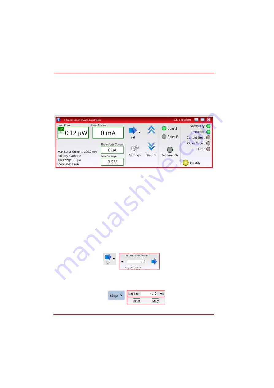
The following screen shot shows the g raphical user interface (GUI) displayed when
accessing the driver using the Kinesis software.
Fig. 6.1 TLD001 Laser Diode Driver Software GUI
Note
. The serial number of th e TLD001 unit associa ted with th e GUI panel is
displayed in the top right hand corner. This information should always be provided
when requesting customer support.
Laser Power display
- shows the output power of the laser diode (P
LD
).
Note
. The
maximum value is de pendent upon he pho todiode current readi ng (I
PD
), the
photodiode current range, set by the rear panel micro switches (Section 3.3.7.), and
the Watts/Amp calibration factor, specified in the Settings panel (see Section 6.2.).
µW and dBm LEDs
- lit when the associated display units are selected.
Laser Current display
- shows the drive curren t applied to the la ser diode (I
LD
).
Note
. The maximum value available is dependent upon the laser diode drive current
limit, set via the Settings panel - see Section 3.3.6.
Set Button
- used to adjust the laser current/power to a specific absolute value, as
set in the pop up window that appears when the button is clicked.
Step Buttons
- used to adjust the output power or current of the laser diode up and
down in steps. The step size is set in the Step Window, displayed by clicking the step
arrow button.


