background image

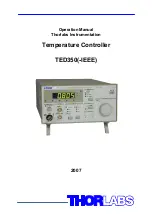
Operation Manual 

Thorlabs Instrumentation 

Temperature Controller  

TED350(-IEEE) 

2007 

Summary of Contents for TED350

Page 1: ...Operation Manual Thorlabs Instrumentation Temperature Controller TED350 IEEE 2007 ...

Page 2: ...Version 2 14 Date 07 02 2007 Copyright 2007 Thorlabs Germany ...

Page 3: ...12 1 7 3 Connecting a temperature sensor AD590 or AD592 13 1 7 4 Connecting a temperature sensor LM135 or LM335 13 1 7 5 Connecting an LM35 14 1 7 6 Connecting the Pt 100 option 15 1 7 7 Connecting a TEC element 15 1 7 8 Connecting the status indicator 17 1 7 9 Fine tuning of the temperature 18 2 Operating the TED350 19 2 1 Manual operation 19 2 1 1 Selecting the sensor 19 2 1 2 Selecting the mode...

Page 4: ... 8 Query Standard Event Status Register ESR 38 3 3 9 Service Request Enable Register SRE 39 3 3 10 Query Status Byte Register STB 39 3 4 System command group 40 3 4 1 Answer mode 40 3 4 2 Error LED mode 40 3 4 3 Querying the error queue 41 3 4 4 Oversampling rate 41 3 5 Status command group 42 3 5 1 Query Device Error Condition Register DEC 42 3 5 2 Query Device Error Event Register DEE 42 3 5 3 D...

Page 5: ... 3 8 7 Reading the STB by serial poll 57 3 8 8 Device error condition register DEC 58 3 8 9 Device error event register DEE 59 3 8 10 Device error event enable register EDE 59 3 9 Hints for setting up control programs 60 4 Maintenance and Repair 63 4 1 General remarks 63 4 2 Cleaning 63 4 3 Selecting the line voltage 64 4 4 Exchanging the line fuse 64 4 5 Troubleshooting 66 5 Service 68 5 1 Exchan...

Page 6: ...from you Thorlabs This part of the instruction manual contains specific information on how to operate the temperature controller TED350 A general description is followed by explanations of how to operate the unit manually You will also find information about remote control via the optional IEEE 488 computer interface Attention This manual contains WARNINGS and ATTENTION label in this form to indic...

Page 7: ...will only apply when the unit is operated correctly Before applying power to your TED350 system make sure that the protective conductor of the 3 conductor mains power cord is cor rectly connected to the protective earth contact of the socket outlet Improper grounding can cause electric shock with damages to your health or even death Also make sure that your line voltage agrees with the voltage ind...

Page 8: ...packaging including the plastic form parts If necessary ask for a replacement package Attention Mobile telephones cellular phones or other radio transmitters are not to be used within the range of three meters of this unit since the electromagnetic field intensity may then exceed the maximum allowed disturbance values according to EN 50 082 1 Attention The temperature controller TED350 must not be...

Page 9: ...ircuit Protection against cable damage bad contact or TEC element with too high resistance Separate over temperature protection Protection against thermal failure Temperature window protection of the laser diode Operation in a specified temperature range Only in combination with a Thorlabs LDC340 Mains filter Protection against line transients or interference s Line failure protection After turnin...

Page 10: ...manual operating elements or by the IEEE488 interface option and a PC Only the TEC current limit value must be set manually No manual settings are required during automatic tests using a PC The set values for temperature thermistor resistance and TEC current const current mode are set with the 10 turn main dial knob The limit values for the TEC current the temperature and the temperature window ar...

Page 11: ...door use only 2 Operation altitude 3000m Warm up time for rated accuracy 10 min Weight 7 kg Dimensions W x H x D including operating elements 220 x 120 x 376 mm3 without operating elements 220 x 110 x 351 mm3 Current output TEC element Control range 5 A 5 A Maximum output power 40 W Compliance voltage 8 V Setting resolution manual remote control 1 mA 0 1 mA Measurement resolution manual remote con...

Page 12: ... resolution remote control 0 1 Ω 1 Ω Accuracy 5 Ω 50 Ω Temperature stability 24 hours 1 0 5 Ω 5 Ω Pt 100 Option Control range 45 C 145 C Setting resolution manual remote control 0 01 C 0 003 C Measurement resolution manual remote control 0 01 C 0 001 C Accuracy 0 3 C Temperature stability 0 005 C Temperature control input Input resistance 10 kΩ Control voltage 10 10 V Transmission coefficient IC s...

Page 13: ...rmistor 10V RWIN 5 Temperature window protection Setting range TWIN 0 5 C 20 C Setting range RWIN 20 kΩ 200 kΩ range 50 Ω 2 kΩ 500 Ω 20 kΩ Computer Interface TED350 IEEE Setting resolution 16 Bit Measurement resolution 11 18 Bit 1 1 Configurable from 11 Bit sign sample rate 18 s to 18 Bit sign sample rate 2 s see chapter 3 4 4 Oversampling rate on page 41 ...

Page 14: ...n F2 Sensor selection field AD590 LM35 Pt 100 Thermistor high Thermistor low F3 TEC output current ON OFF switch F4 Mains power control switch F5 Modulation input and analog voltage output BNC F6 Display selection field F7 Operating mode selection Const current const temperature resistance F8 PID temperature control loop settings F9 Main dial knob 10 turn I I F1 F2 F3 F4 F5 F6 F7 F8 F9 ...

Page 15: ...B1 Fan air outlet B2 Temperature window output for LDC340 B3 IEEE488 interface jack B4 Mains voltage selector B5 Fix Set values determined by potentiometers Var Adjustable by main dial B6 Unit wakeup settings DIP switch B7 TEC output jack 15 pin D SUB jack B8 DIP switch for interface settings B9 Mains jack with fuse holder ...

Page 16: ...ature or the minimum allowed resistance Check the type of temperature sensor in your setup Select this sensor in the field marked SENSOR Select the display TSET LIM Change the limit value of the temperature or resistance to the desired value with the screwdriver potentiometer next to the LED TSET LIM 1 6 3 Setting the temperature window Check the type of temperature sensor in your setup Select thi...

Page 17: ...the output jack Pin Connector TEC element 5 6 7 TEC element 13 14 15 TEC element ground 2 Voltage detector TEC element 9 Voltage detector TEC element Status indicator 1 Status LED 8 Status LED ground Temperature sensor 3 Thermistor ground 4 Thermistor 10 AD590 592 Pt 100 11 AD590 592 Pt 100 12 Supply voltage for Thorlabs mounts 8 7 6 5 4 3 2 1 15 14 13 12 11 10 9 ...

Page 18: ... a thermistor all temperatures are shown in ohms therefore you have to look for the corresponding temperature in the datasheet of the thermistor Figure 4 Connecting a thermistor When the actual temperature TACT is chosen for display the thermistor resistance is shown The pushbutton F2 Figure 1 selects the resistance range of the thermistor In position TH 20 kΩ the maximum thermistor range is 20 kΩ...

Page 19: ...9 If the thermistor characteristic R T is given in the data sheet the desired resistance can be read directly 1 7 3 Connecting a temperature sensor AD590 or AD592 The IC temperature sensor of the AD590 family is set up between pin 10 and pin 11 These sensors translate the temperature into an equivalent current that can be displayed and set directly in C 10 11 Figure 5 Connecting an AD590 or AD592 ...

Page 20: ...r LM335 you must select AD590 as temperature sensor 1 7 5 Connecting an LM35 The IC temperature sensor of the LM35 series is set up between pin 10 pin 11 and pin 8 These sensors will map the temperature into an equivalent voltage that can be displayed and set directly in C 11 10 8 Figure 7 Connecting an LM35 LM35 out ...

Page 21: ...de of the Pt 100 to pin 3 and 10 the other side to pin 4 and 11 of the D SUB connector For optimum performance use a separate wire for each pin of the D SUB connector and connect the corresponding wires only at the Pt 100 and not at the D SUB connector 1 7 7 Connecting a TEC element The plus pole of the TEC must be connected to the pins 5 6 7 the minus pole to the pins 13 14 15 of the output jack ...

Page 22: ...in 2 and pin 9 may also be connected directly in the plug at the jack i e pin 2 with pin 5 6 7 and pin 9 with pin 13 14 15 but this leads to a measurement error due to the voltage drop in the lines to the TEC element Then a slightly too high voltage is displayed 13 15 14 7 5 6 9 2 Figure 9 Connecting the TEC element Attention A TEC element connected with wrong polarity may lead to thermal runaway ...

Page 23: ...ally running away from TSET the TEC element is reverse connected Change the polarity and repeat the procedure If TACT is settling up and down evenly around the value TSET the TEC element is connected correctly however the values for the P I and D share of the control loop are still incorrect Refer to chapter 2 2 2 PID adjustment starting on page 26 If TACT is settling properly to the value TSET th...

Page 24: ...r mode The purpose is for example to stabilize the wavelength of laser diodes in closed control loops wavelength locker The input has no low frequency limit If a DC voltage is applied a constant deviation from the set temperature can be achieved The upper frequency limit depends on the thermal setup especially on the thermal load It will be in the range of some Hertz When fine tuning the temperatu...

Page 25: ...nsor Three different types of sensors can be selected AD590 family LM35 family Pt 100 for TED350 with Pt 100 option Thermistor low range Thermistor high range A LED indicates the selected sensor 2 1 1 1 The Pt 100 option Select the LM35 as sensor The Pt 100 is operated with a constant current of 1 mA flowing from pin 4 to pin 3 The display shows the temperature in C with an accuracy of 1 C over th...

Page 26: ... current ITEC LIM Set temperature resistance TSET TEC current ITEC Size of the temperature window TWIN Maximum allowed temperature minimum allowed resistance TSET LIM Actual temperature resistance TACT TEC voltage UTEC A LED indicates the selected display NOTE In constant TEC current mode some values i e TSET are not defined and can not be displayed or even selected With the output switched off an...

Page 27: ...e output 20 C leads to 0 V at the output 25 C leads to 10 V at the output 2 1 5 Switching the output ON and OFF With the button TEC ON the TEC current is switched on or off The LED inside this button indicates the state of the output 2 1 6 Setting the PID shares Refer to chapter 2 2 Optimization of temperature control loops starting on page 24 2 1 7 WIN OUT This jack can be used to supervise the t...

Page 28: ...ocated on the front panel indicate the position of this switch If the switch position is changed during TEC ON the TEC output will be switched off automatically 2 1 9 Wakeup setting DIP switch This DIP switch offers the following functions SW1 and SW2 select the default wakeup sensor when switching the unit on SW1 SW2 function up up AD 590 up down TH 20kΩ down up LM 35 down down TH 200kΩ SW3 selec...

Page 29: ...indow protection SW4 function up TWIN active down TWIN disabled SW5 selects whether the beeper is on or off SW5 function up beeper on down beeper off SW6 selects whether the I share of the regulator loop is active or not SW6 function up I share active down I share off SW7 and SW8 are not used ...

Page 30: ...onnecting the component to the source sink copper alu A propulsion to lead the flow of heat TEC element laser sensor copper bloc TEC element heat sink Statements and implications The temperature of the laser can be measured with the sensor In the copper bloc is a heat flow between laser and TEC element In the TEC element is a heat flow between copper bloc and heat sink In the heat sink is a heat f...

Page 31: ...perature Influences on the real temperature control loop To 1 Offset and gain errors of the sensor will only allow a relative knowledge of the laser temperature The sensor is never fixed to the laser chip in such a way that it will exclusively measure its temperature So the temperature in the copper bloc being inho mogeneous due to the heat flow is measured as well Even within the laser chip the t...

Page 32: ...an be selected independently Example of a PID adjustment Preconditions All limit values all polarities have been set correctly a suitable sensor is connected and selected the ambient temperature is about 20 C 1 Set the P and D share to 0 7 o clock 2 Switch off the I share SW6 of the DIP switch on the rear Refer to chapter 2 1 9 Wakeup setting DIP switch starting on page 22 3 Switch on the output b...

Page 33: ...ots The D share has been set correctly when the actual temperature remains stable on a value near the set temperature after a minimum of overshoots I share 6 Switch on the I share again SW6 of the DIP switch on the rear Refer to chapter 2 1 9 Wakeup setting DIP switch starting on page 22 7 Again change repeatedly between set temperatures of about 18 C and 22 C while observing the settling behavior...

Page 34: ...ead and written in SI units i e A not mA W not mW etc Letters may be written in small or capital letters Attention Before programming a TED350 first set the limit value of the TEC current ITEC LIM hardware limit for the used TEC element with a screwdriver The corresponding potentiometer is marked ADJ and located next to the LED ITEC LIM at the front of the TED350 The value ITEC LIM is constantly m...

Page 35: ...EEE488 jack at the rear of the unit The address of the TED350 must differ from that of other devices on the IEEE488 bus Please refer to chapter 3 1 2 Setting up the interface on page 30 3 1 1 IEEE 488 Interface subsets Function Part set Source Handshake SH1 Acceptor Handshake AH1 Talker T6 Listener L4 Service Request SR1 Remote Local RL1 Parallel Poll PP0 Device Clear DC1 Device Trigger DT0 Electr...

Page 36: ...to SW5 have to be set according to Table 2 Address SW5 SW4 SW3 SW2 SW1 0 Off Off Off Off Off 1 Off Off Off Off On 2 Off Off Off On Off 3 Off Off Off On On 4 Off Off On Off Off 5 Off Off On Off On 6 Off Off On On Off 7 Off Off On On On 8 Off On Off Off Off 9 Off On Off Off On 10 Off On Off On Off 11 Off On Off On On 12 Off On On Off Off 13 Off On On Off On 14 Off On On On Off 15 Off On On On On con...

Page 37: ...n Off On On On 24 On On Off Off Off 25 On On Off Off On 26 On On Off On Off 27 On On Off On On 28 On On On Off Off 29 On On On Off On 30 On On On On On or Off Table 2 IEEE 488 address setting NOTE The device address is valid after switching off and on again Terminator The string terminator of the TED350 is preset to LF EOI This is fixed and cannot be changed The TED350 will accept any combination ...

Page 38: ... than 2 meters and the total cable length should not exceed 20 meters The TED350 IEEE will automatically enter REMOTE mode after the first character is transferred NOTE Programming the control software will vary with the type of computer the user interface the programming language the interface card used as well as with the driver software and the correspondingly supplied software interfaces Pleas...

Page 39: ...licitly produced in the control program Also in the LabVIEW or LabWindows CVI drivers from Thorlabs these functions are implemented When receiving the IEEE488 bus commands GET LLO GTL DCL or SDC the TED350 executes the following functions LLO Local Lockout The command LLO disables the button Return to LOCAL mode manual operation is only possible with the command GTL see below GTL Go To Local The c...

Page 40: ...itched on anew but will be in REMOTE mode NOTE The command DCL sets back all units connected to the IEEE488 bus SDC Selected Device Clear The command SDC switches the output off and sets back all values that are usually set back when switching the unit on The TED350 will behave as if it has been switched on anew but will be in REMOTE mode NOTE In contrast to the command DCL the command SDC only se...

Page 41: ...f a program message contains a query command i e a command which requests a response the TED350 returns a response message Program messages With program messages settings are done command at the TED350 and response messages are selected query Program messages can be separated by semicolon All program messages are executed sequentially one after the other Examples MODE CC selecting the mode constan...

Page 42: ...l value with sign in integer notation Examples 1 or 1 or 22 or 14356789432 Refer to IEEE488 2 1992 standard chapter 8 7 2 Numeric response data Type 2 NR2 Is a numerical value with or without sign in floating point notation without exponent Examples 1 1 or 1 1 or 22 1 or 14356 789432 Refer to IEEE488 2 1992 standard chapter 8 7 3 Numeric response data Type 3 NR3 Is a numerical value with or withou...

Page 43: ...ILE TED350 0 2 17 Description A reply consists of the following sequence Manufacturer Model Serial No Firmware version 3 3 2 Reset Syntax RST Description All set values will be reset to the default values The output is switched off 3 3 3 Self test query Syntax TST Response 0 Description 0 Self test finished successful 3 3 4 Set Operation complete bit Syntax OPC Description The TED350 sets the OPC ...

Page 44: ...ogramming Syntax ESE NR1 Valid Range 0 255 Default Value 0 Description Sets the Event Status Enable Register ESE Reading Syntax ESE Response NR1 Description Queries the Event Status Enable Register ESE and returns the content in decimal notation The content is not modified 3 3 8 Query Standard Event Status Register ESR Syntax ESR Response NR1 Description Queries the Standard Event Status Register ...

Page 45: ...ble Register SRE Reading Syntax SRE Response NR1 Description Queries the Service Request Enable Register ESE and returns the content in decimal notation The content is not modified 3 3 10 Query Status Byte Register STB Syntax STB Response NR1 Description Queries the Status Byte Register STB and returns the content in decimal notation Bit 6 MSS is set to 0 the other bits are kept un changed ...

Page 46: ... ACT 5 123456E 02 This is not according to the IEEE488 2 standard but useful if you want to increase speed Reading Syntax SYST ANSW Response SYST ANSW FULL SYST ANSW VALUE Description Queries the answer mode 3 4 2 Error LED mode Programming Syntax SYST ERRLED OFF SYST ERRLED ON Default Value OFF Description When switched to ON the interface ERRor LED lights as long as there are errors in the error...

Page 47: ...r 3 7 Error messages of the TED350 starting on page 49 3 4 4 Oversampling rate Programming Syntax SYST OSR NR1 Valid Range 0 7 Default Value 5 Description Sets the TED350 oversampling rate see table below Reading Syntax SYST OSR Response NR1 Description Queries the oversampling rate Sampling rate Resolution Measurement speed 0 11 Bit sign 18 s 1 12 Bit sign 13 s 2 13 Bit sign 10 s 3 14 Bit sign 8 ...

Page 48: ...ery Device Error Event Register DEE Syntax STAT DEE Response NR1 Description Queries the Device Error Event Register DEE and returns the content in decimal notation The content is cleared 3 5 3 Device Error Event Enable Register EDE Programming Syntax STAT EDE NR1 Valid Range 0 65535 Default Value 0 Description Sets the Device Error Event Enable Register EDE Reading Syntax STAT EDE Response NR1 De...

Page 49: ...sor Sets the programmed temperature resistance current to default values Reading Syntax SENS Response SENS AD SENS LM SENS THL SENS THH Description Queries the type of temperature sensor 3 6 2 Operation mode MODE Programming Syntax MODE CC constant current MODE CT constant temperature resistance Assumption The TEC output is switched off Description Selects the mode of operation Sets the programmed...

Page 50: ...ion Queries the state of the TEC output 3 6 4 Reading the TEC current hardware limit LIMTP Syntax LIMTP ACT Response LIMTP ACT NR3 Description Queries the actual TEC current hardware limit Unit A Refer to Chapter 1 6 1 Setting the limit value of the TEC current on page 10 3 6 5 Reading the TEC temperature resistance hardware limit LIMTR Syntax LIMTR ACT Response LIMTR ACT NR3 Description Queries t...

Page 51: ...e sensor is set to AD590 or LM35 Description Queries the programmed temperature Unit C Reading the minimum temperature Syntax TEMP MIN Response TEMP MIN NR3 Assumption The temperature sensor is set to AD590 or LM35 Description Queries the minimum allowed temperature Unit C Reading the maximum temperature Syntax TEMP MAX Response TEMP MAX NR3 Assumption The temperature sensor is set to AD590 or LM3...

Page 52: ... sensor is set to thermistor high or low range Description Queries the programmed thermistor resistance Unit Ω Reading the minimum resistance Syntax RESI MIN Response RESI MIN NR3 Assumption The temperature sensor is set to thermistor high or low range Description Queries the minimum allowed thermistor resistance Unit Ω Reading the maximum resistance Syntax RESI MAX Response RESI MAX NR3 Assumptio...

Page 53: ...ng the set current Syntax ITE SET Response ITE SET NR3 Description Queries the programmed TEC current Unit A Reading the minimum current Syntax ITE MIN Response ITE MIN NR3 Description Queries the minimum allowed TEC current Unit A Reading the maximum current Syntax ITE MAX Response ITE MAX NR3 Description Queries the maximum allowed TEC current Unit A Reading the actual current Syntax ITE ACT Res...

Page 54: ...CT Response WIN ACT NR3 Description Queries the actual temperature resistance window Depending on the temperature sensor the temperature window or the resistance window is retuned Unit C Ω 3 6 10 Reading the TEC voltage VTE Syntax VTE ACT Response VTE ACT NR3 Description Queries the actual TEC voltage Unit V ...

Page 55: ...ntil the error queue is empty refer to 3 4 3 Querying the error queue on page 41 The error queue can keep 32 errors If the queue is empty the error message 0 No error is sent to the PC 3 7 1 General errors 0 No error Category None Possible reason The error queue is empty 100 Unknown command Category Command Error Possible reason HELLO WORLD This string sent to the TED350 was not recognized as vali...

Page 56: ... THL This compound is not valid for this command 190 Parser buffer overflow Category Command Error Possible reason The string sent to the TED350 was too long for the parser 200 Data out of range Category Execution Error Possible reason TEMP SET 10E 30 sent to the TED350 but this temperature is much too high 300 Hardware error Category Device Error Possible reason Many Device must probably be maint...

Page 57: ... There is no data in the output buffer 500 IEEE488 receive buffer overflow Category Device Error Possible reason The string sent to the TED350 was too long for the IEEE488 receive buffer 250 char max 3 7 2 TED350 operation error messages 1103 Over temperature Category Execution Error Possible reason Internal temperature too high Wait until the TED350 has cooled down Maintain proper air flow 1104 W...

Page 58: ... mode Category Execution Error Possible reason The TEC current may not be affected during constant temperature mode 1111 No setting of temperature resistance during constant current mode Category Execution Error Possible reason The temperature resistance may not be affected during constant current mode 1112 Limit of temperature resistance reached Category Execution Error Possible reason The set va...

Page 59: ...TB ESE and SRE and three 16 bit registers DEC DEE and EDE to program various service request functions and status reporting Please refer to the IEEE488 2 1992 standard chapter 11 Figure 10 The service request and standard event registers Output buffer ERROR Queue or serial poll Service Request Generation ...

Page 60: ...3 8 Status reporting TED350 page 54 Figure 11 The device Error registers DEC DEE and EDE STAT DEC n Slot number Temperature out of window ...

Page 61: ...or occurred Request control Not used Operation complete Can be set with OPC The ESR can be read directly with the command ESR This read command clears the ESR The content of the ESR can not be set The bits are active high 3 8 2 Standard event status enable register ESE The bits of the ESE are used to select which bits of the ESR shall influence bit 5 ESB of the Status Byte Register STB The 8 bits ...

Page 62: ...long as there are errors in the error queue FIN command finished This bit is high after a command has finished and all bits of the STB have been set The STB can be read directly with the command STB The content of the STB can not be set The bits are active high All bits except bit 6 of the STB can be used to assert a service request SRQ Please refer to 3 8 5 Alternatively the SRQ can be recognized...

Page 63: ...Q 3 8 6 Reading the STB by STB command If the controller does not listen to SRQs at all the service request can be detected by reading the status byte with the command STB If bit 6 is logical 1 a service request was asserted 3 8 7 Reading the STB by serial poll If the controller does not support auto serial poll the service request can also be detected via manual serial poll If bit 6 is logical 1 ...

Page 64: ...h Wait until the TED350 has cooled down Maintain proper air flow 4 Temperature window The TED350 asserted a temperature window protection signal 5 Open circuit The TED350 detected the TEC element to have a too high resistance or being not present 6 No sensor The TED350 detected no sensor connected to the output jack 7 Temperature limit The TED350 detected the temperature to reach the temperature r...

Page 65: ...et Reading clears the DEE 3 8 10 Device error event enable register EDE The bits of the EDE are used to select which bits of the DEE shall influence bit 3 DES of the STB The 8 bits of the EDE are related by logical AND to the according 8 bits of the DEE These 8 results are combined by logical OR so that any hit leads to a logical 1 in bit 3 DES of the STB As any bit of the STB can assert an SRQ ev...

Page 66: ...e IEEE488 interface Use this sequences to ensure a fast and secure communication Flowchart for writing device commands Figure 12 Device commands flowchart Start writing Write command to device ibwrt Poll status byte ibrsp Is FIN bit set No Yes Yes No Is EAV bit set Is FIN bit set No Yes Poll status byte ibrsp Query error queue write SYST ERR to the device Read error message ibrd Yes No Is EAV bit ...

Page 67: ...Read device messages flowchart Start reading Write query to device ibwrt Poll status byte ibrsp Is FIN bit set No Yes Yes No Is EAV bit set Is FIN bit set No Yes Poll status byte ibrsp Query error queue write SYST ERR to the device Read error message ibrd Yes No Is EAV bit set End Read device message ibrd ...

Page 68: ...into the pro gramming text and accomplish the data transfer between control computer and TED350 We recommend to build these write and read back com mands into separate functions and then use these functions for the data transfer In these functions a globally to set flag should be requested that would determine whether the write or read back communication is to be read out together with talker and ...

Page 69: ...our Thorlabs technical hotline before sending the device to Thorlabs Germany for repair 4 2 Cleaning Inspect the instrument as often as operating conditions require To clean the exterior surface perform the following steps 1 Remove loose dust on the outside of the instrument with a lint free cloth Use care to avoid scratching the clear plastic display filter 2 Use a soft cloth dampened with water ...

Page 70: ...that the switch has clicked into one of the three positions and is not between positions Attention When changing the line voltage please do also change the mains fuse to the appropriate value 4 4 Exchanging the line fuse If the line fuse has opened due to line disturbances incorrectly set voltage or other influences from the outside it can be exchanged at the rear without opening the unit Attentio...

Page 71: ...located at the rear part of the drawer Figure 14 Changing the mains fuse Remove the fuse holder completely and exchange the defective fuse We would recommend to check the replacement fuse at the same time and change her also to the appropriate value Put the fuse holder back until is has snapped in Execute a function test of the TED350 by switching it on In case the TED350 could not be switched on ...

Page 72: ...the rear panel of the TED350 If the fuse has opened replace the fuse by the correct type refer to 4 4 Exchanging the line fuse on page 64 You don t get the desired operation temperature Is the hardware limit ITEC LIM set to 0 Adjust the hardware limit IMAX by means of the potentiometer on the TED350 front panel to an appropriate value Is the TEC connected properly to the front connector Check all ...

Page 73: ...ies of the temperature sensor refer to chapters 1 7 2 to 1 7 6 Select the corresponding temperature sensor manually or with the SENS XY command If you don t find the error source by means of the trouble shooting list please first connect the Thorlabs Hotline before sending the TED350 for checkup and repair to Thorlabs Germany refer to section 6 7 Addresses on page 76 ...

Page 74: ...m the mains power With the TED350 turned over remove the two screws that secure the cover to the chassis Remove the unit by sliding it out of the cover With the unit set upright you will find the label depicting names values and positions of internal fuses at the outer wall of the transformer section Replace the defective fuse and reattach the cover T10A250V LDC 340 TED 350 Si3 Si5 Si4 Internal Fu...

Page 75: ...orlabs warrants the hard and software determined by Thorlabs for this unit to operate fault free provided that they are handled according to our requirements However Thorlabs does not warrant a fault free and uninterrupted operation of the unit of the soft or firmware for special applications nor this instruction manual to be error free Thorlabs is not liable for consequential damages Restriction ...

Page 76: ...nce criterion C IEC 61000 4 5 Power Line Surge Immunity Performance criterion C IEC 61000 4 6 Conducted RF Immunity Performance criterion B IEC 61000 4 11 Voltage Dips and Interruptions Immunity Performance criterion C EN 61000 3 2 AC Power Line Harmonic Emissions Complies with the Radiocommunications Act and demonstrated per EMC Emission standard1 2 3 AS NZS 2064 Industrial Scientific and Medical...

Page 77: ...rements for electrical equipment for measurement control and laboratory use Additional Compliance IEC61010 1 A2 1995 Safety requirements for electrical equipment for measurement control and laboratory use Equipment Type Test and measuring Safety Class Class 1 as defined in IEC 61010 1 Annex H grounded product 6 3 Thorlabs End of Life policy WEEE As required by the WEEE Waste Electrical and Electro...

Page 78: ...rlabs or your nearest dealer for further information 6 3 1 Waste treatment on your own responsibility If you do not return an end of life unit to Thorlabs you must hand it to a company specialized in waste recovery Do not dispose of the unit in a litter bin or at a public waste disposal site 6 3 2 Ecological background It is well known that WEEE pollutes the environment by releasing toxic products...

Page 79: ...6 3 Thorlabs End of Life policy WEEE TED350 page 73 Figure 15 Crossed out wheelie bin symbol ...

Page 80: ...S Device Error Status DIN Deutsche Industrie Norm DIP Dual In line Package DUT Device Under Test EAV Error AVailable EDE Enable Device Error Event Register EOI End Of Information ERR ERRor ESE Standard Event Status Enable register ESR Event Status Register FIN Command FINished GET Group Execute Trigger GTL Go To Local IEEE Institute for Electrical and Electronic Engineering I Share Integral share ...

Page 81: ...ments on front panel 8 Figure 2 Operating elements on rear panel 9 Figure 3 Pinning of the output jack 11 Figure 4 Connecting a thermistor 12 Figure 5 Connecting an AD590 or AD592 13 Figure 6 Connecting a LM135 or LM335 14 Figure 7 Connecting an LM35 14 Figure 8 Connecting the Pt 100 option 15 Figure 9 Connecting the TEC element 16 Figure 10 The service request and standard event registers 53 Figu...

Page 82: ...date contact information USA Canada and South America Thorlabs Inc sales thorlabs com techsupport thorlabs com Europe Thorlabs GmbH europe thorlabs com France Thorlabs SAS sales fr thorlabs com Japan Thorlabs Japan Inc sales thorlabs jp UK and Ireland Thorlabs Ltd sales uk thorlabs com techsupport uk thorlabs com Scandinavia Thorlabs Sweden AB scandinavia thorlabs com Brazil Thorlabs Vendas de Fot...

Reviews: