LC1 – USB / USB 2.0 CCD Line Camera/ page 29
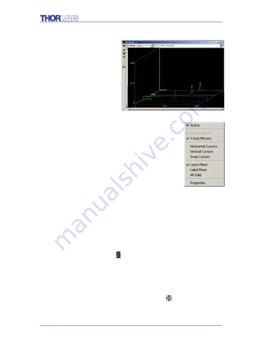
The screen now appears as in the figure below:
In this example, it is important that
the background noise has been
filtered out. In the 3D view, the
offsets are clearly shown, as can be
seen in this close-up view of the
right edge of the plot window. As
expected, the offsets are displayed
in the INPUT and BACKGROUND
layers, but not in the SIGNAL layer.
3.3.9.
Cursors
A number of different cursor and display features can be
accessed through right clicking of the mouse. In the plot window,
click the right mouse button. This image should appear. Each of
the options will now be explained:
Active
– determines whether the window is running or not. This
is particularly useful when there are multiple plot windows being
displayed.
Cursor Labels
– mark the cursor with labels such as x1 or x2 so the cursor may be
easily identified.
X-Axis Microns
– switches between measurement of microns and pixel number.
When it is checked, the measure is in microns.
Horizontal Cursors
– draws a pair of horizontal cursors that may be moved from up
and down to define a region of interest. When the mouse is moved over a horizontal
cursor line the arrow will change to . While the mouse is in this state, holding down
the left mouse button will allow the horizontal cursor line to be dragged. A readout is
given that gives the location of y1, y2, and the difference between y1 and y2. The
readout may be dragged to anywhere on the plot window, by holding down the left
mouse button while the mouse pointer is over it. With Horizontal Cursors displayed,
clicking on the Zoom to current horizontal cursors button
(
on the toolbar on the
left side
) will zoom to the area between the Horizontal Cursors.


