background image


LC1 – USB / USB 2.0 CCD Line Camera/ page 15   


The following dialog box will appear: 


To change the label, click on the edit window above Device Label, type the new 

label, and click OK. 

Note:

  The label can only be modified while the LC1-USB is in the idle state. 


3.2. 

First Time Start 

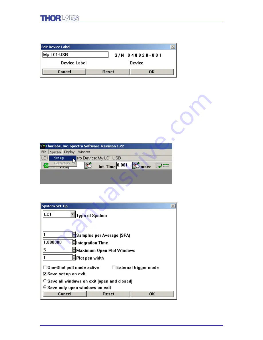
If this is the first time starting the line camera there are a couple of settings that must 

be checked. Left-click on System 

 Set-Up on the menu bar. 


The following menu will appear: 


Summary of Contents for LC1 - USB

Page 1: ...Operation Manual Thorlabs LC1 USB USB 2 0 CCD Line Camera 2005 ...

Page 2: ......

Page 3: ...Version 2 0 Date 28 Nov 05 Copyright 2005 Thorlabs GmbH Germany ...

Page 4: ......

Page 5: ...ol 18 3 3 2 Layer Changing Example 19 3 3 3 Current Layer 22 3 3 4 Averaging Smoothing 22 3 3 4 1 Averaging 22 3 3 4 2 Smoothing 22 3 3 5 Peak Finder 23 3 3 6 Gaussian Transform 23 3 3 6 1 Gaussian Plot 24 3 3 6 2 Gaussian Distribution of a Beam 24 3 3 7 Mathematical Functions 28 3 3 8 3D View 28 3 3 9 Cursors 29 3 4 Storing and Retrieving Data 30 3 5 Multi Save Storage Feature 31 3 6 Collecting E...

Page 6: ...5 LC1 USB Specifications 36 5 1 Dimensions 37 6 Addresses 38 7 Warranty 39 7 1 WEEE 40 7 1 1 Waste treatment on your own responsibility 40 7 1 2 Ecological background 41 ...

Page 7: ...r ideas We and our international partners are looking forward to hearing from you Thorlabs GmbH This part of the instruction manual contains specific information on how to operate an LC1 USB USB 2 0 CCD Line Camera manually and by remote control Attention This manual contains WARNINGS and ATTENTION label in this form to indicate dangers for persons or possible damage of equipment Please read these...

Page 8: ......

Page 9: ... assist 2 Installation 2 1 Parts List Below is a list of all components shipped with the LC1 USB Qty Description 1 LC1 USB USB2 0 CCD Line Camera 1 LC1 USB User Manual 1 CD ROM with LC1 USB Software 1 USB2 0 A B Cable 2 Meter 2 2 Connections The LC1 USB must NOT be connected to your PC while the software is being installed Once the software has been installed connect the host connector of the USB ...

Page 10: ...am Autorun exe Mouse click on the Install Software menu button to install the application program Spectra To install the USB driver for the LC1 USB make sure the LC1 USB is NOT plugged in to a USB port then click on the Install Jungo menu button For Windows 9X systems the menu program cannot be used to install the driver Instead open a DOS window and CD to the CDROM directory USB Utilities and run...

Page 11: ...the license conditions of National Instruments when you use the full version of NI VISA A note on USB USB devices are recognized by the host through their identifiers VID vendor identifier and PID product identifier These IDs are 16bit unsigned integer values Thorlabs PID is 1313HEX The factory setting for the LC1 USB is 0010HEX and this is the PID used by the Jungo USB drivers and spectra For use...

Page 12: ...ll of the installation instructions have been followed it is now time to run the line camera software Go to the Start Menu Thorlabs spectra exe The screen that appears is as follows Note The message No Device appears in the status bar This indicates the LC1 USB is not connected to a USB port ...

Page 13: ...e display should resemble the following Note Status bar indicates the LC1 USB device My LC1 USB is attached The status bar shows there is an LC1 USB device attached with the Device Label My LC1 USB You may change the Device Label by pulling down the Display menu and opening to Set Device Label ...

Page 14: ...above Device Label type the new label and click OK Note The label can only be modified while the LC1 USB is in the idle state 3 2 First Time Start If this is the first time starting the line camera there are a couple of settings that must be checked Left click on System Set Up on the menu bar The following menu will appear ...

Page 15: ...y number greater than one represents the number of samples averaged together for the data displayed Int Time is the integration time This represents how sensitive the CCD is to incoming light CCD pixels act like light buckets gathering photons The integration time display represents how many milliseconds the bucket is open For very bright sources low integration times are required whereas for weak...

Page 16: ... Bars Scroll bars are used to scale the graphical output in the plot window The image to the right shows a portion of the vertical scroll bar The vertical scroll bar controls the relative amplitude of the peaks of a line scan that is being viewed Move the cursor around the bar The cursor symbol will change from to when the cursor is in a position to change the vertical scale While in that position...

Page 17: ...ulb represents whether or not the layer is displayed in the plot window represents that the layer is on and represents that it is off The lock specifies whether the layer may be changed is unchangeable and may be changed This function allows access to another menu that controls the math functions acting on the data Any layer with the exception of Layer0 may be made up of existing layers in combina...

Page 18: ...mple here are the steps so the input line is doubled Step 1 Click on the icon in order to bring up the layer control menu In the example there were no previous layers so only Layer0 appeared If there are other layers it is simple to highlight them and remove them The screen that comes up looks as follows Step 2 Click on the Add button as in the picture and Layer1 will appear that can now be used t...

Page 19: ...menu Click on the color for Layer1 to bring up the color menu This allows the choice of color for the display To change the color click on the color square or use the RGB red green blue sliders to make a new color Step 6 To change the line type that Layer1 will display in click on the line for Layer1 as shown to the right This will allow a number of different choices Then click on OK to continue T...

Page 20: ... the plot window can be shifted into 3D mode To do this move the cursor to the origin where there is a small red dot When the cursor is over the small red dot it will change from to At this point hold down the left mouse button and move the cursor towards the center of the plot window This will cause the plot to fold out in 3D The resulting effect should look like this image More about 3D views wi...

Page 21: ... increase the value and backward to decrease the value Note When decreasing values in this manner it is very easy to decrease the value to zero This can cause errors such as division by zero that will stop the polling of the line camera 3 3 4 Averaging Smoothing 3 3 4 1 Averaging The averaging routine uses the SPA Samples Per Average function This function is accessible through the main toolbar Av...

Page 22: ...h 5 iterations The exact number of iterations to use on a data set is usually determined with trial and error 3 3 5 Peak Finder The LC1 USB has a function that is specifically designed to find peaks The peak finding function looks for local maxima and represents them as a plot similar to a delta function with the relative intensity of the maxima This is a very convenient way to compare multiple pe...

Page 23: ... example of the use of this function follows 3 3 6 2 Gaussian Distribution of a Beam The diagram below shows the raw input of laser diode module In order to define the Gaussian characteristics extra layers will be added Clicking on the layer icon brings up the layer menu In order to define the Gaussian characteristics extra layers will be added Clicking on the layer icon brings up the layer menu ...

Page 24: ...wing image This is also a good time to change the color of each layer as shown BACKGROUND The layer called BACKGROUND will be a sample with the laser turned off To define this layer the math menu is brought up and the definition of the layer should be entered as INPUT To capture the background noise physically block the source Use the lock symbol to ensure that the signal does not change when the ...

Page 25: ...ath icon S for the SIGNAL layer and enter the formula When the SIGNAL layer is displayed alone it appears as follows The SIGNAL is really just the INPUT layer with the offset subtracted out GAUSSIAN The final layer is the GAUSSIAN layer To make this clearer we must first switch to pixels rather than microns for the units being displayed To do this first right click anywhere in the plot window The ...

Page 26: ...own below With these starting values the Gaussian can be continuously adjusted to find the best match for the displayed peak In the above case after manipulating the three variables the screen becomes as indicated in the next figure below This indicates that the center is at pixel 1914 the peak is 0733 and the width is 051 The width is very useful for determining the 1 e2 diameter The 1 e2 diamete...

Page 27: ...use of mathematical functions This can easily be bypassed By using the predefined function on a layer a math function can be performed on a newly created layer 3 3 8 3D View When working with multiple layers it is often convenient to be able to see all of them separately In the example of the Peak Finder function there were a total of four layers being displayed One way to see the layers is to tur...

Page 28: ...g displayed Cursor Labels mark the cursor with labels such as x1 or x2 so the cursor may be easily identified X Axis Microns switches between measurement of microns and pixel number When it is checked the measure is in microns Horizontal Cursors draws a pair of horizontal cursors that may be moved from up and down to define a region of interest When the mouse is moved over a horizontal cursor line...

Page 29: ... mouse button while is on a vertical cursor to change its location Layer Plane boxes the current layer In the 2D view this has no effect but in the 3D view it helps in distinguishing which layer is current and being operated on All Solid makes the graphical output opaque for each layer It helps in visualization when doing a monochromatic printout of the 3D view In the 2D view it acts to partially ...

Page 30: ...tion file for storing the data or browse if the file already exists Select the source layer for the captured data the total number of scans to be captured and the integer number of scans to be skipped between captured scans Note that if Scans to Skip is zero every scan is captured until the total number of Scans to Record is achieved Once the Multi Save setup is complete activate Multi Save mode b...

Page 31: ...l is applied to the trigger input 4 Troubleshooting 4 1 In the Win2000 and XP Operating System The USB device driver file WINDRVR6 SYS must be located in C WINNT system32 drivers For Win2000 and XP systems the driver files WINDRVR6 INF and THORLABS INF must be located in C WINNT INF You must have administrator privileges to install and run the LC1 USB application spectra exe When the driver softwa...

Page 32: ...HORLABS INF must be located in C WINDOWS INF When the driver software is installed by running the man_install_9x bat program the driver files are copied to the appropriate system directories and registered Following installation and connecting the LC1 USB the Found New Hardware wizard may launch The wizard should automatically find the driver and install it If the wizard is unable to find the driv...

Page 33: ...l the driver close the LC1 USB application disconnect your LC1 USB insert the LC1 USB CDROM and mouse click the Uninstall Driver button On Windows 9X systems you will need to open a DOS window and CD to the CDROM directory USB Utilities and run the batch file man_uninstall_9x bat Reboot your PC Reconnect your LC1 USB to the USB port Verify the device icon Jungo with Thorlabs Linear CCD Camera is n...

Page 34: ...ME Win2000 or XP Windows 95 or versions of NT earlier than 5 0 are not supported and will cause the installation to fail The spectra software comes on a CDROM Mount the CDROM and a menu program should launch If this fails run the CDROM program CD Starter CD Starter exe In order for you to install and run spectra in the Win2000 or XP environments you must have administrative privileges Are there an...

Page 35: ...s 0 21301µm Points Scalable Y axis 0 10 000Units Scalable Data Display Continuous or One Shot Poll Mode Data Update Better than 90Hz CPU Speed Dependant PC Requirements 500MHz Pentium III or Higher with 256MB RAM Hard Drive CD ROM Dedicated USB 2 0 Port Optical Head Spectral Range 350 to 1000nm CCD Integration Time 1µs to 200ms CCD Sensitivity 300V lx s CCD Pixel Size 7µm x 200µm 7µm pitch Dimensi...

Page 36: ...LC1 USB USB 2 0 CCD Line Camera page 37 5 1 Dimensions ...

Page 37: ...f Germany Tel 49 0 81 31 5956 0 Fax 49 0 81 31 5956 99 Email europe thorlabs com Internet http www thorlabs com Our company is also represented by several distributors throughout the world Please call our hotline send an E mail to ask for your nearest distributor or just visit our homepage http www thorlabs com ...

Page 38: ...Thorlabs GmbH warrants the hard and software determined by Thorlabs GmbH for this unit to operate fault free provided that they are handled according to our requirements However Thorlabs GmbH does not warrant a faulty free and uninterrupted operation of the unit of the soft or firmware for special applications nor this instruction manual to be error free Thorlabs GmbH is not liable for consequenti...

Page 39: ... not disassembled and not contaminated As the WEEE directive applies to self contained operational electrical and electronic products this end of life take back service does not refer to other Thorlabs products such as Pure OEM products that means assemblies to be built into a unit by the user e g OEM laser driver cards Components Mechanics and optics Left over parts of units disassembled by the u...

Page 40: ...during decomposition The aim of the European RoHS directive is to reduce the content of toxic substances in electronic products in the future The intent of the WEEE directive is to enforce the recycling of WEEE A controlled recycling of end of live products will thereby avoid negative impacts on the environment Fig 1 crossed out wheelie bin symbol ...

Reviews: