THORLABS Kinesis PFM450E User Manual Download Page 40

Page 37

ETN018233-D03

PFM450E Piezo Focus Mount and Controller


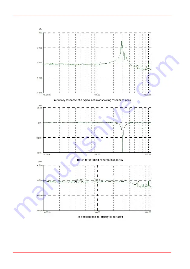
As the resonance frequency of  actuators varies with load in  addition to  the minor

variations from product to product, the notch filter is tuneable so that its characteristics

can be adjusted to match those of the actuator. In addition to its centre frequency, the

bandwidth of the notch (or the equivalent quality factor, often referred to as the Q-

factor) can also be adjusted. In simple terms, the Q factor is the center frequency/

Summary of Contents for Kinesis PFM450E

Page 1: ...HA0358T PFM450E Piezo Focus Mount and Controller Kinesis User Guide Original Instructions...

Page 2: ...1 Unpacking 6 3 2 Mounting 7 3 2 1 General 7 3 3 Installing the Focus Mount 7 3 4 Fitting Changing the Objective 9 3 4 1 Angular Rotation 10 3 5 Installing the Controller 11 3 5 1 Siting 11 3 5 2 Envi...

Page 3: ...Piezos 25 4 7 Using the Controller as a Piezo Amplifier 26 4 8 Thermal Shutdown 27 4 9 Using the MZF001 Joystick 27 4 10 Load Response 28 Chaper 5 Software Reference 29 5 1 GUI Panel 29 5 2 Settings P...

Page 4: ...These sensors give correct positioning with submicron repeatability and resolution on the order of 1 nm in open loop and 3 nm in closed loop making this product ideal for applications that require hig...

Page 5: ...d ease of use adjustment of many key parameters is possible through direct interaction with the graphical panel For example the output drive voltage or position can be adjusted by entering a value in...

Page 6: ...cribed in more detail in the following section 1 2 2 Kinesis Server With the Kinesis system Net Controls are deployed to allow direct control over and also reflect the status of the range of electroni...

Page 7: ...ers and client application developers to interact seamlessly with the Kinesis hardware Each of the Kinesis controllers has an associated Net Control and these are described fully in the handbooks asso...

Page 8: ...ot specified by the manufacturer the protection provided by the equipment may be impaired In particular excessive moisture may impair operation Spillage of fluid such as sample solutions should be avo...

Page 9: ...t contains no user servicable parts Do not remove any screws securing the covers or attempt any repairs or adjustments as this will affect the calibration and invalidate the warranty Adjustments are c...

Page 10: ...the travel is not obstructed If the mount is driven against a solid object damage to the internal mechanism could occur The range of travel is 450 m in closed loop but can be up to 600 m in open loop...

Page 11: ...tighten the clamp bolt until resistance is felt then a further 1 4 turn Caution Proper alignment and positioning is crucial to correct functioning of the piezo mount When fitting ensure that the mount...

Page 12: ...hex key supplied loosen the lower clamping bolt Fit the adapter to the focus mount ensuring that the mounting flange on the adapter sits flush against the body of the piezo mount Re tighten the clamp...

Page 13: ...t for more details Fig 3 4 Angular rotation Caution Due to its inherent capacitance movement or vibration of the cable may affect the stability of the stage Where possible arrange the cable in such a...

Page 14: ...conditions before being powered up Caution Ensure that proper airflow is maintained to the sides of the unit Warning Operation outside the following environmental limits may adversely affect operator...

Page 15: ...empting to install If you experience any problems when installing software contact Thorlabs on 44 0 1353 654440 and ask for Technical Support Note When operating via a PC direct user interaction with...

Page 16: ...g the device must understand the hazards associated with using high voltages and the steps necessary to avoid risk of electrical shock The piezo controller must be switched OFF before the focus mount...

Page 17: ...ller Note The Simulator utility can be used to set up simulated hardware configurations and place the Kinesis Server into simulator mode In this way it is possible to create any number and type of sim...

Page 18: ...ontrols the position The input impedence is 10 k load 0 to 10V gives 0 to 450um in closed loop and 2V to 10V gives 30V to 150V in open loop In cases where there is a software contribution 10V to 10V c...

Page 19: ...ection for serial port communication see Section A 3 USB USB port for system communications Caution Before the input can be used the Drive Input Source must be set to a BNC SW option in the Settings p...

Page 20: ...g in Closed Loop mode If the LED is not lit the unit is operating in open loop Error LED Lit when one of the following fault conditions occur 1 One or more power supply voltages are out of range 2 Clo...

Page 21: ...r is linearized in the digital domain and for maximum accuracy the linearizing curve is individually matched to the sensor The setpoint position is maintained by a PID controller whose coefficients ca...

Page 22: ...able Notch Filter fc fc f f Tunable Low Pass Filter Notch Frequency and Bandwidth Notch Filter On Off Tunable Notch Filter fc f Derivative Cut Off Frequency position setpoint Proportional coefficient...

Page 23: ...to a file which simplifies system set up whenever the software is run up This tutorial shows how the Kinesis application provides all of the functionality necessary to operate the hardware 1 Fit the f...

Page 24: ...is likely to result if the objective mount is driven by a different controller or if the controller is used to drive other objective mounts Warning Risk of Electrical Shock The piezo actuators in this...

Page 25: ...n outputting a constant voltage the piezo controller continuously monitors the position signal and if necessary adjusts the output voltage to maintain the required position 4 4 Tuning Note The PPC001...

Page 26: ...the settling time is optimised increase P I and D with 10 increments until position display indicates a large ringing effect in the range of microns Consider this point as threshold for stability 12...

Page 27: ...set before the position attained by a specific applied voltage and the position attained by a corresponding specified distance can be rationalized This is particularly important when operating in ope...

Page 28: ...pup Window 2 In the Step Size field enter a step size in the range 0 1 V to 10 V This can be entered directly into the field or by clicking on the up down arrows 3 Click Apply to save the settings and...

Page 29: ...5 Click OK to save the settings and close the window Any voltage on the rear panel BNC connector is now amplified by the unit and presented at the HV OUT piezo drive connector and the position of the...

Page 30: ...ntuitive tactile manual positioning It is used in conjunction with a PPC001 piezo controllers Furthermore if the parameter settings are saved persisted to the controller the controller need not be con...

Page 31: ...E Mar 2022 Page 28 Chapter 4 PC Operation Tutorial 4 10 Load Response The response of the PPC001 to varying load and frequencies is shown below Fig 4 4 Response of PPC001 to Varying Loads and Frequenc...

Page 32: ...left corner of the display Set Arrow Opens the settings window so that the target drive voltage or position can be entered see Section 4 6 2 Step Arrows used to increment or decrement the output volt...

Page 33: ...e functions on this Control refer to the Kinesis API helpfile for further details 5 2 1 Persisting Settings to the Hardware Many of the parameters that can be set for the PPC001 Piezo Controller can b...

Page 34: ...tick BNC the unit sums all three signals Output Mode the EXT OUT BNC connector on the rear panel can be used to monitor the piezo actuator on an external device e g oscilloscope This can be a useful C...

Page 35: ...feedback associated with the actuator being driven either Capacitive or Strain Gauge The PFM450 piezo mount has a capacitive sensor and this parameter is locked MMI Display Display Intensity In some...

Page 36: ...ollows Proportional Gain The Proportional parameter makes a change to the output which is proportional to the current error value A high proportional gain results in a large change in the output for a...

Page 37: ...ssible to tune the PID loop using slider controls To display these controls click the Tune button These slider controls adjust the settings for the PID parameters and any changes are applied immediate...

Page 38: ...to display a slider control which can be used to make adjustments and monitor the effect on the system Notch Filter Settings Due to their construction most actuators are prone to mechanical resonance...

Page 39: ...v E Mar 2022 Page 36 Chapter 5 Software Reference adjustable electronic anti resonance that can be used to counteract the natural resonance of the mechanical system Fig 5 5 Notch filter settings v loa...

Page 40: ...variations from product to product the notch filter is tuneable so that its characteristics can be adjusted to match those of the actuator In addition to its centre frequency the bandwidth of the not...

Page 41: ...specified in Hz in the range 20 to 500 default 100 Alternatively click the Tune button to display a slider control which can be used to make adjustments and monitor the effect on the system Optimizin...

Page 42: ...igh Voltage Ground Return 2 Unused 9 Unused 3 Unused 10 Stage ID 4 Sinewave Excitation Output 11 Low Voltage Ground 5 Unused 12 Low Voltage Ground 6 15 V Preamplifier Supply 13 Piezo ID Legacy Stages...

Page 43: ...ound 13 Digital I P 4 5 9 10 6 Digital I P 1 5 9 10 14 5V Supply Output 5 9 10 7 Digital I P 2 5 9 10 15 5V Supply Output 5 9 10 8 Digital I P 3 5 9 10 Warning Do not under any circumstances attempt t...

Page 44: ...s The digital outputs used here can be used to directly drive most optocouplers and the 5V supply available on pins 14 and 15 can be used to provide power for the optocouplers Fig A 4 Application Exam...

Page 45: ...V Please see the Kinesis helpfile for details on software calls used to control these logic IO A 2 4 Trigger Output The trigger output is different from the rest of the digital outputs in that it is...

Page 46: ...switch the inputs will read as logic LOW if the switch is open circuit and HIGH if the switch is closed When connected to a logic output or any other voltage source the input is guaranteed to read LO...

Page 47: ...ed for connecting to a host PC The pin functions are detailed in in Fig A 8 Fig A 8 RS232 Connector Pin Identification A 4 Rear Panel Joystick Connector Provides connection to the MZF001 joystick The...

Page 48: ...e equipment contains no user servicable parts There is a risk of electrical shock if the equipment is operated with the covers removed Only personnel authorized by Thorlabs Ltd and trained in the main...

Page 49: ...nm Closed Loop Resolution 3 nm Typical Settling Time for 1 to 100 m Step 25 ms Position Linearity Error 0 05 Resonant Frequency for 150 g Load 120 Hz 20 Max Load any direction 500g 1 1 lb Tilt Angle...

Page 50: ...10 V to 10 V DC Absolute Maximum Input Voltage 20 V DC Input Voltage for Full Range 10 V DC 2 External Output BNC Output Voltage Range 0 to 10 V nominal for full range output can swing negative in ce...

Page 51: ...ystick Compatible with Thorlabs MZF001 Joystick Closed Loop Algorithm Digital PID with Dual Tuneable Notch Filter Processor DSP 32 bit Floating Point 160 MHz ARM Cortex M4F Servo Update Interval 50 s...

Page 52: ...ng piezo is very large typically hundreds of newtons Perhaps the most useful property of these actuators is their ability to produce oscillating motion at considerable frequencies usually limited by t...

Page 53: ...he sensor measures the position the circuit subtracts the measured position from the demand position to get the error and a proportional integral feedback loop adjusts the voltage to the actuator unti...

Page 54: ...closed loop control is a linear relationship between demand voltage and measured position see Fig D 4 in contrast to open loop control see Fig D 2 Fig D 4 Closed loop response amp actuator demand mov...

Page 55: ...harmful interference when the equipment is operated in a commercial environment This equipment generates uses and can radiate radio frequency energy and if not installed and used in accordance with t...

Page 56: ...Page 53 ETN018233 D03 PFM450E Piezo Focus Mount and Controller E 2 CE Certificate...

Page 57: ...Rev E Mar 2022 Appendix E Regulatory Page 54...

Page 58: ...see right were sold to and are currently owned by a company or institute within the EC and are not dissembled or contaminated Contact Thorlabs for more information Waste treatment is your own respons...

Page 59: ...www thorlabs com...

Reviews: