


CM201
Chapter 4: Getting Started
Rev G, January 28, 2022
Page 5
4.2.
Setting up the CM201
CAUTION
DO NOT place the SMA to BNC cable or DB-25 Connector cable near any electrical noise sources
such as a power cable. This may cause poor quality images.
A. Microscope
1.
Use four screws (M6 for metric/1/4-20x5/8" for imperial) to mount the CM201 onto the optical table.
See the
Mechanical Drawing Chapter on Page 26
for mounting holes.
2.
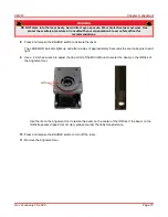
Use the 2 mm hex wrench to remove the shipping plate on the objective arm.
3.
Use the 3/32" hex key to remove the locking screw and move the slider to the front of the microscope.
4.
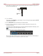
Use two screws and washers to mount the K-Cube Stepper Motor Controller onto the optical table.
5.
Connect the cable from the Motorized Objective Arm to the
Motor
port of the K-Cube Stepper Motor
Controller.
6.
Connect the K-Cube Power Supply to a standard power outlet.
7.
Connect one end of the USB cable to the K-Cube Stepper Driver Controller and the other end to the
computer.
Summary of Contents for CM201
Page 1: ...CM201 Green Fluorescent Protein Confocal Microscope User Guide ...
Page 4: ......
Page 12: ...CM201 Chapter 4 Getting Started Page 8 TTN118795 D02 4 3 Cable Connection Diagram ...
Page 30: ...CM201 Chapter 8 Mechanical Drawing Page 26 TTN118795 D02 Chapter 8 Mechanical Drawing ...
Page 33: ...www thorlabs com ...


