


A
PPENDIX
A, C
HIPPER
C
HECK
35
PRELIMINAR
Y
PROCEDURE USING
“SELECT CHASSIS”:
1. Apply AC power to the instrument and wait 20 seconds for it to reach “Standby” mode.
2. Enter the service menu by pressing and holding “<VOL DN> and <CH DN>” for 8 seconds.
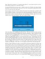
3. When the service menu appears, scroll to “Miscellaneous” and press “OK”.
4. Select “Bus Quiet” by holding down the “OK” button for >2.5 seconds to place the set in Chipper
Check Mode.
5. With the PC and Chipper Check Interface connected, start Chipper Check and highlight the
ITC222 under “Select Chassis” on the main menu.
6. Follow the on screen instructions to establish a Chipper Check connection with the chassis.
NOTE:
It is suggested to fill out the information screen with at least a model and serial number
and save the information.
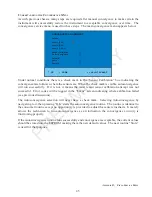
7. Enter the “EEPROMs” tab on the Chipper Check screen and select “Replace SSB Board
Procedure”.
8. Press <Copy SSB to File>. Chipper Check will prompt for a file name. Be certain to give the
file a name that can be associated with only this chassis (the chassis serial number is recommended).
The EEPROM data will be stored in the customer file location normally used by Chipper Check.
9. Remove AC power from the instrument, disconnect the Chipper Check connector from the
chassis, then change the SSB board. Shut the Chipper Check software down.
10. Using an alligator clip or jumper wire, enable EEPROM writing by shorting the two pins of
BK200 together. BK200 is located on the replacement SSB at location I9.
11. Apply AC power to the chassis and allow the instrument to enter standby mode.
12. Enter the service menu by pressing and holding “<VOL DN> and <CH DN>” for 8 seconds.
13. When the service menu appears, scroll to “Miscellaneous” and press “OK”.
14. Select “Bus Quiet” by holding down the “OK” button for >2.5 seconds to place the set in Chipper
Check Mode.
15. Now start Chipper Check and highlight the ITC222 under “Select Chassis” on the main menu.
16. Follow the on screen instructions to establish a Chipper Check connection with the chassis.
NOTE
: It is suggested to open the previously saved customer information screen.
17. Again enter the “EEPROMs” tab, and select “Replace SSB Board Procedure”. This time press
<Paste File to SSB>. Chipper Check will prompt for a file name. Be certain to select the
previously stored file associated with this chassis. The stored EEPROM data will be placed into
the new SSB EEPROM locations.
18. When the upload is completed, disconnect Chipper Check, remove AC power from the chassis
and remove the jumper from BK200. Wait at least 30 seconds for the chassis to power completely
down.
19. Proceed to “
T
RANSFER
N
EW
A
LIGNMENTS
TO
EEPROM
”


