ITC222 Geometry & Convergence Procedures
23
C
ONVERGENCE
T
EMPLATE
D
ESIGN
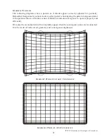
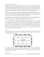
The convergence pattern is developed on specific formulas intended to provide consistent linearity
and uniformity from one instrument and screen size to the next. The best template to return an
instrument to factory appearance is the internally generated patterns. If an original pattern is not
available because all three CRT’s must be changed or the SSB module must be replaced without the
benefit of saving the original convergence EEPROM data, then an external template must be
provided for the technician to place the instrument back to manufacturing specification.
There are two types of templates available for reconverging the ITC222 instrument line; mylar and
string. Part number MTITC222 contains individual mylar templates for the four common screen
sizes, 40”, 52”, 56” and 61”. The kit will be availabable on the TSN website beginning the second
half of 2005. Check the website for pricing and specific availability.
The templates are fixed to the inside of the screen frame and provide a full convergence pattern.
Typically only Level 3, 15x13 alignments are required when this template is available as raster size,
linearity and position are set by matching the onscreen pattern to the template.
If the mylar templates are unavailable a simple string pattern may be used. Using a few strings,
math, a measuring device, masking tape, carpenters string and a formula, an accurate template
may be easily made. Using the 5x5 Level 2 convergence points, algorithms in the convergence
microprocessor will roughly locate most convergence points setting both raster size, position and
linearity very closely. Then using the 15x13 Level 3 adjustment convergence can be dialed in
more precisely. Remember the 5x5 menu is only meant as a “course” alignment however making
several full rounds will locate the convergence points closer and closer reducing the time required
in the more labor intense 15x13 alignment.
C
AUTIONS
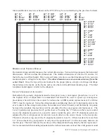
Do not place marks on the frame to locate the strings. Begin by placing 3” strips of masking tape
at the approximate frame locations shown. Mark the measurement points in pencil on the tape
rather than directly on the frame.
Place 3" Strips
of Masking Tape
along Frame
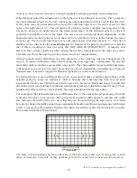
The strings may now be stretched over the pencil mark for accuracy. Once the string has been
properly located, fix its position by placing another piece of tape over it. (A second piece of tape
on the side of the frame may help hold string tension better.) The final string template will appear
similar to the above example.
C
ENTERLINE
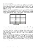
The string template is based on knowing the precise location of the vertical and horizontal


