ITC222 Geometry & Convergence Procedures
14
C
ENTERING
R
ING
A
DJUSTMENT
Centering Ring adjustment
is not
required under the following circumstances.
•
If no CRT’s, CRT Drivers or main yokes were changed, centering ring adjustment should
not be necessary and it is highly recommended not to move or otherwise adjust them!
•
If an SSB module has been replaced that may otherwise cause geometry or convergence
issues, as long as a CRT or main yoke
was not changed
, the centering rings do not require
adjustment!
Centering Ring adjustment may be required for the following circumstances.
•
If only one CRT, CRT Driver Board or Main Yoke was replaced use the convergence pattern
and centering rings for the replacement color to align the pattern back to the patterns on the
CRT’s not replaced.
•
If multiple CRTs, CRT driver boards or Main Yokes have been replaced Centering Ring
adjustment will be required.
To begin Centering Ring adjustment disconnect the convergence amplifiers from the convergence
yoke (connector BW001/002) thereby providing a pattern free from convergence influence for the
next steps.
1. Connect the proper signals to provide sync to the instrument. Centering Ring alignment is
not dependant on the deflection frequency but the pattern generator needs sync to provide a
stable display.
2. Enter the service menu from the standby mode by pressing and holding CH DN and VOL DN
for more than 8 seconds.
3. Select the proper input by pressing the “Input” button on the remote until the desired signal
is onscreen or select a channel by direct access via the remote control.
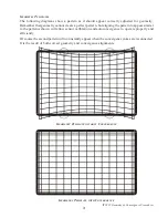
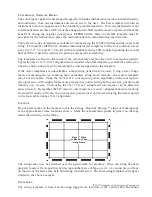
4. In the service menu select and enter the Convergence menu. Select the Level 3 (15X13)
adjustment menu and press OK. Then enter the pattern by selecting “Alignment Mode”
and again press OK. This brings up the convergence pattern which makes an excellent
reference for geometry related adjustments.
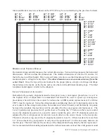
5. Toggle through the patterns by pressing “OK” until all three colors are visible. The color
patterns will be offset from each other with Green being closest to exact center. The
following steps depend on the repair. Always align a replacement CRT or yoke to the ones
not replaced!
6. If Green was replaced, use the centering rings on the green CRT to place the center crosshair
of the convergence pattern in the center of the screen both horizontally and vertically. (If
Green was not replaced, do not move it! Align the red or blue CRT pattern to the green.)
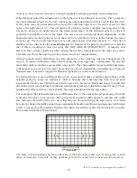
7. If red or blue was replaced adjust the Red and Blue crosshair such that the center horizontal
lines lay exactly on top of the green center line. Adjust the Red crosshair such that the
center vertical line is to the left of the Green or the Blue crosshair such that the center
vertical line is to the right of the Green. Use the following table to determine how far right
or left the lines should be.


