

TA04864 E Page 8 of 13
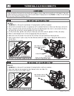
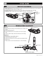
Terminal Sensor
CL
Screw
Adjust Left / Right
Anvil
Terminal Censor
Centered
FRONT OF STOCK GUIDE
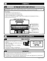
Overview:
1. Sensor locates the position of the terminal/disconnect in relation to the
tooling.
2. Default position setting of ‘0’.
3. The terminal/disconnect is to be centered over the anvil for proper
crimp.
4. Adjust as needed to align center terminal/disconnect with tooling.
Adjustment:
1. Set position to ‘0’ (see section 6, step 6.4).
2. Loosen terminal sensor lock screws.
3. Adjust sensor left/right to move terminal/disconnect position left/right.
4. Tighten screw.
5. Visually confirm center of terminal/disconnect is in line with tooling.
TERMINAL SENSOR ADJUSTMENT
7.2
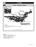
WIRE STOP ADJUSTMENTS
7.1
1.
Bench Top Presses:
Wire stop will allow user to insert the wire into the terminal/disconnect at correct depth (See
terminal/disconnect documentation for depth value).
2.
Automated Presses:
Wire stop will aid in the removal of the terminal/disconnect from ram tooling.
3.
Adjustment:
Height / Depth: Adjust to desired position with screws in locations shown.
BACK END OF STOCK GUIDE
Wire Stop
Depth
Adjustment
Screw
Height
Adjustment
Screw
7.0
STOCK GUIDE


