
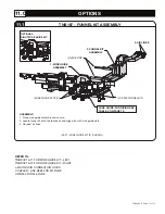

DELAY MODE CALIBRATION
6.5
Delay
Selection
Approximate Delay
(seconds)
0
0
1
0.2
2
0.4
3
0.6
4
0.8
5
1
6
1.5
7
2
8
3
9
5
TABLE III
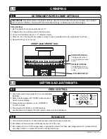
1. Set and adjust the Delay that occurs between the
triggering of the feed cycle and the start of the feed cycle
(Feed cycle is triggered by movement of ram or by
pressing ‘FEED’ button on display).
2. There are 9 Delays available as defined in Table III.
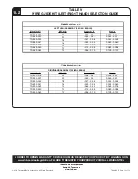
CL
ADJUST LEFT / RIGHT
Left Limit:
-50
Default Setting:
0
Right Limit:
+50
CENTERED
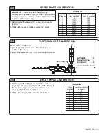
Position Mode Calibration:
1. Left-to-right adjustments of the terminal/disconnect
relative to the tooling.
2. Each value represents 0.001” of shift to the right or the left.
POSITION MODE CALIBRATION
6.4
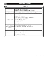
Speed
Selection
Approximate Speed
(mm / second)
Approximate Speed
(inches / second)
1
6.35
0.25
2
12.70
0.50
3
19.05
0.75
4
25.40
1.00
5
31.75
1.25
6
38.10
1.50
7
50.80
2.00
8
63.50
2.50
9
76.20
3.00
TABLE II
1. Set and adjust the Speed of the carrier strip during the
feed cycle.
2. There are 9 Speeds available as defined in Table II.
IMPORTANT:
The feed cycle is the advancing
movement of the carrier strip. This cycle is initiated after
crimping in order to feed a new terminal/disconnect into
alignment with crimp tooling.
SPEED MODE CALIBRATION
6.3
TA04864 E Page 7 of 13


