

6.0
SETTING ADJUSTMENTS
RUN MODE
6.2
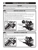
1. Terminals/disconnects will automatically feed when Run Mode is selected.
2. Run Mode will also be auto initiated by movement of the ram.
3. Run mode will run with the speed, delay, and position values that have been programmed. If no adjustments
have been made, run mode will function with default values.
FEED CONTROL
6.1
MODE
LOCK
UP/FEED
DOWN
COUNT
RUN
POSITION
DELAY
SPEED
1. The Automated Crimping System has (4) adjustable
‘MODES’.
2. Select desired mode with ‘MODE’ button on feed
control screen display.
3. Mode values are adjusted via the ‘UP/FEED’ &
‘DOWN’ buttons.
4. Pressing the ‘UP/FEED’ & ‘DOWN’ buttons
simultaneously will display the total number of feed cycles completed.
0
48
42
42
6
12
12
6
0
48
CONDUCTOR DIAL
The higher the value is
set, the tighter the crimp
will be.
INSULATION DIAL
The higher the value is
set, the tighter the crimp
will be.
DIAL INDICATOR
CRIMP ADJUSTMENT DIAL
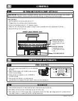
IMPORTANT:
Recommended crimp height settings, specific to terminal or disconnect tooling, are provided
with tool packs. Before crimping with recommended settings, calibrate per instructions below.
DETERMINE PROPER CRIMP SETTINGS
Crimp Setting:
1. Set Conductor Dial and Insulator Dial to “0”.
2. If applicable, close saftey guards. Restore power.
3. Crimp terminal/disconnect or 1/4” diameter solder.
4. Measure the crimp height and compare values to layout provided with the appropriate Tool Pack.
5. Record Settings for future use.
5.1
5.0
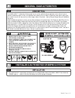
CRIMPING
TA04864 E Page 6 of 13


