Page
|
16
PE
Enhanced
Mains
Protector
EN/IEC 61643
PATENT
APPLIED
FOR
LL
'
L2
L2'
L3
L3'
NN
'
11
14
12
ST
ATUS
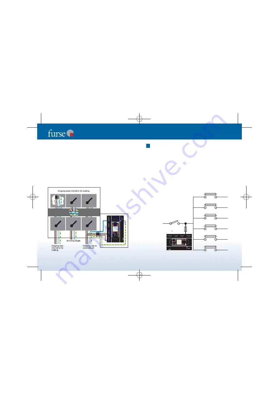
Figure 11 -
Connection for
supplies continuing
external to the
building.
(b) Protecting supplies going out of the building
The connection methods 8a (i to iii) are not suitable for
protecting a power distribution board which provides a
supply to outside the building - either to a separate building
or some other external load (eg site lighting).
To protect the equipment inside the building, from transient
overvoltages entering the board on the outgoing feed,
protection should be installed close to the external load.
See Figure 11.
Isolation
It is good practice to be able to isolate or disconnect the
ESP unit from the supply. The supply to the entire
distribution board should not be switched off on many
computer power supplies and other critical loads.
The means of isolation should therefore be installed in the
connection to the ESP unit.
Figures 12 & 13 show example
connection schematics
. Where it is also necessary to fuse
the connection to the ESP unit
(see 10 - Fuse connecting
leads)
this can be achieved through use of a switchfuse,
MCCB or type ’C’ MCB.
9
Incoming
supply
fused F
S
HRC switch fuse or MCCB
F
SPD
, where F
SPD
< 0.5 F
S
PE
Enhanced
Mains
Protector
EN/IEC 61643
PATENT
APPLIED
FOR
L
L'
L2
L2'
L3
L3'
N
N'
11
14
12
STATUS
Figure 12 - ESP unit
installed on incoming side
of distribution board.
Page
|
17
Installation instructions for mains wire-in protectors
TNB 1639 ESP D1 Instructions (Final Art) new size 1/4/10 09:51 Page 16


