background image

Step

Screw (quantity)

Color

Torque

2

M2 × 5 mm, small-head, nylon-coated (4)

Black

0.181 Nm
(1.85 kgf-cm)

3

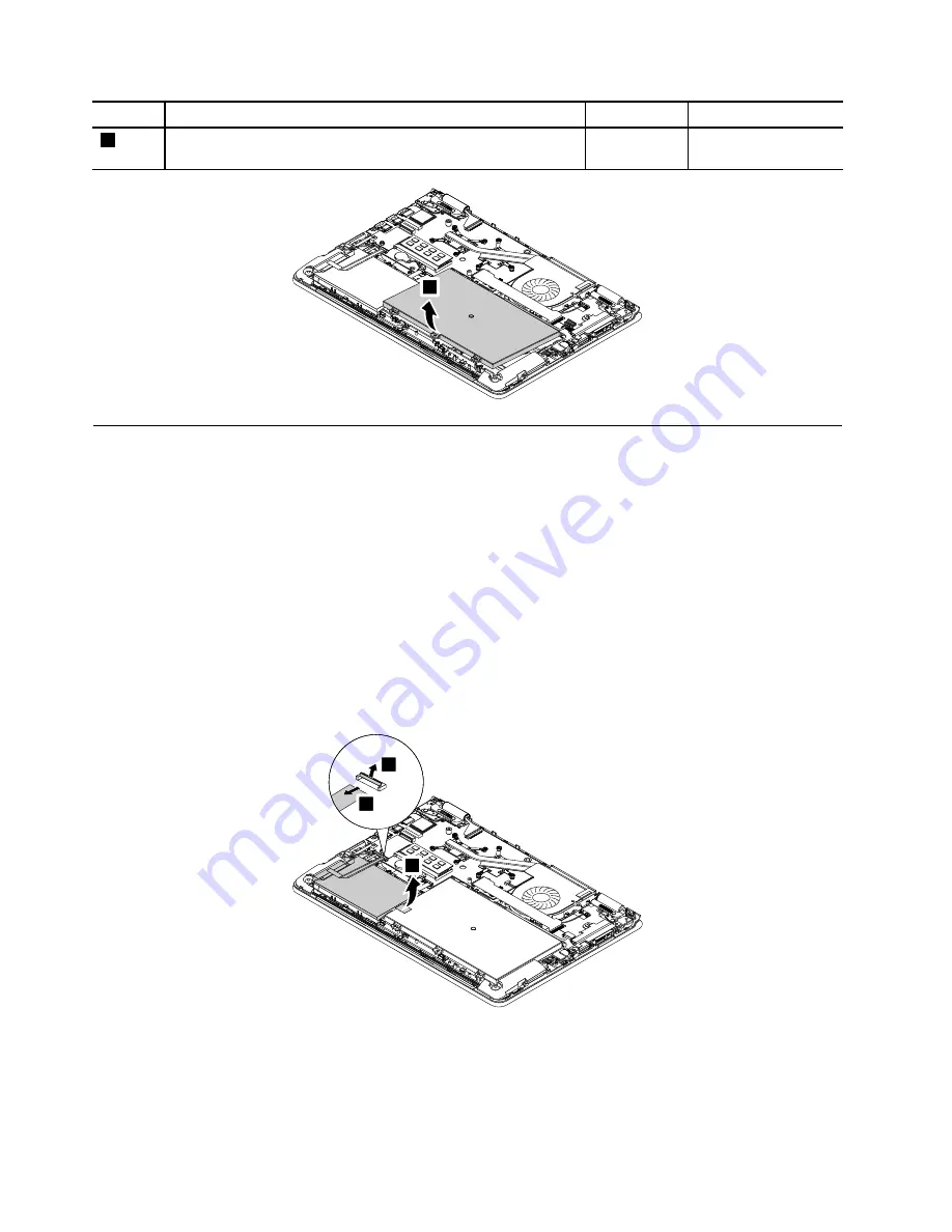
1050 Internal storage drive and the storage drive connector

For access, remove this FRU:

“1030 Base cover assembly” on page 63

Attention:

• Do not drop the drive or apply any physical shock to it. The drive is sensitive to physical shock. Improper

handling can cause damage and permanent loss of data.

• Before removing the drive, have the user make a backup copy of all the information on it if possible.

• Never remove the drive while the system is operating or in suspend mode.

Removal steps of storage drive and the storage drive connector

Disconnect the storage drive connector from the system board and remove the storage drive together with
the storage drive connector.

3

1

3

2

66

Hardware Maintenance Manual

Summary of Contents for Yoga 14

Page 1: ...Hardware Maintenance Manual ThinkPad Yoga 14...

Page 2: ...der Appendix A Notices on page 91 First Edition October 2014 Copyright Lenovo 2014 LIMITED AND RESTRICTED RIGHTS NOTICE If data or software is delivered pursuant a General Services Administration GSA...

Page 3: ...d Windows 8 1 operating system 30 Refreshing your computer 30 Resetting your computer to the factory default settings 31 Using the advanced startup options 31 Recovering your operating system if Windo...

Page 4: ...embly 73 1130 ThinkPad logo LED card 74 1140 Media card reader 75 1150 System board 75 1160 Thermal fan 77 1170 Keyboard bezel assembly and LCD unit 78 2010 LCD bezel assembly 80 2020 LCD module 81 20...

Page 5: ...bleshoot problems Important This manual is intended only for trained service technicians who are familiar with ThinkPad products Use this manual along with the advanced diagnostic tests to troubleshoo...

Page 6: ...iv Hardware Maintenance Manual...

Page 7: ...toolcase away from walk areas so that other people will not trip over it Do not wear loose clothing that can be trapped in the moving parts of a machine Make sure that your sleeves are fastened or ro...

Page 8: ...afety sections of maintenance information Use extreme care when measuring high voltages Regularly inspect and maintain your electrical hand tools for safe operational condition Do not use worn or brok...

Page 9: ...r pinched cables 9 Check that the power supply cover fasteners screws or rivets have not been removed or tampered with Handling devices that are sensitive to electrostatic discharge Any computer part...

Page 10: ...ents Electrical grounding of the computer is required for operator safety and correct system function Proper grounding of the electrical outlet can be verified by a certified electrician Safety notice...

Page 11: ...DANGER DANGER DANGER DANGER DANGER Chapter 1 Safety information 5...

Page 12: ...6 Hardware Maintenance Manual...

Page 13: ...PERIGO PERIGO PERIGO PERIGO Chapter 1 Safety information 7...

Page 14: ...PERIGO PERIGO PERIGO PERIGO DANGER 8 Hardware Maintenance Manual...

Page 15: ...DANGER DANGER DANGER DANGER DANGER DANGER Chapter 1 Safety information 9...

Page 16: ...DANGER VORSICHT VORSICHT VORSICHT VORSICHT 10 Hardware Maintenance Manual...

Page 17: ...VORSICHT VORSICHT VORSICHT VORSICHT Chapter 1 Safety information 11...

Page 18: ...12 Hardware Maintenance Manual...

Page 19: ...Chapter 1 Safety information 13...

Page 20: ...14 Hardware Maintenance Manual...

Page 21: ...Chapter 1 Safety information 15...

Page 22: ...16 Hardware Maintenance Manual...

Page 23: ...Chapter 1 Safety information 17...

Page 24: ...18 Hardware Maintenance Manual...

Page 25: ...placing parts Ensure that all software fixes drivers and UEFI BIOS downloads are installed before replacing any FRUs listed in this manual After a system board is replaced ensure that the latest UEFI...

Page 26: ...s displayed begin the diagnosis with the first error code Whatever causes the first error code may also cause false error codes If no error code is displayed see whether the error symptom is listed in...

Page 27: ...Services 3 Click Check Warranty Status 4 On the Warranty Status Lookup page click Parts Lookup 5 Type your machine type and serial number and then click Submit eSupport also can be used to view the ge...

Page 28: ...22 Hardware Maintenance Manual...

Page 29: ...failures can occur for a variety of reasons that have nothing to do with a hardware defect such as cosmic radiation electrostatic discharge or software errors Consider replacing a FRU only when a pro...

Page 30: ...ook computers Note The diagnostic tests are intended to test only ThinkPad products The use of non ThinkPad products prototype cards or modified options can lead to false indications of errors and inv...

Page 31: ...rage devices view system information and check and recover bad sectors on internal storage devices To run the UEFI diagnostic program do the following 1 Turn on the computer If the computer cannot be...

Page 32: ...l be launched automatically 5 Follow the instructions on the screen to use the diagnostic program If you have created the bootable diagnostic medium on a CD do the following 1 Turn on the computer If...

Page 33: ...orrect replace the ac power adapter 4 If the voltage is acceptable replace the system board Note Noise from the ac power adapter does not always indicate a defect Checking the built in battery and ope...

Page 34: ...m board Checking the coin cell battery To check the coin cell battery do the following 1 Disconnect the battery connector See Disabling the built in battery on page 60 2 Remove the coin cell battery S...

Page 35: ...recovery process Applications and Drivers Recovery Disc one or more discs This disc restores the preinstalled applications and drivers on the computer Supplemental Recovery Disc This disc contains add...

Page 36: ...Recovery overview for the Windows 8 and Windows 8 1 operating system This section provides information about the recovery solutions for the Windows 8 and Windows 8 1 operating systems A Windows recove...

Page 37: ...s To perform a complete format click Fully clean the drive to start the process The process will take several hours 4 Follow the instructions on the screen to reset your computer to the factory defaul...

Page 38: ...of the following For Windows 8 Type recovery in the Search field and click Settings Then click Create a recovery drive For Windows 8 1 Type recovery in the Search field and click the Search button Th...

Page 39: ...ur are servicing does not perform well and the problem might be caused by a recently installed program you can refresh the computer without losing the customers personal files or changing the settings...

Page 40: ...operating system can be started For instructions on how to remove the power on password see How to remove the power on password on page 35 Hard disk password There are two kinds of hard disk password...

Page 41: ...ogo comes up immediately press F1 3 Type the supervisor password to enter the ThinkPad Setup program 4 Select Security 5 Select Password 6 Select Power On Password 7 Type the current supervisor passwo...

Page 42: ...he hard disk drive hybrid drive or solid state drive is powered off The microprocessor stops To enter sleep mode do one of the following For Windows 7 Click the arrow beside the Shut down icon and the...

Page 43: ...hybrid drive or solid state drive Symptom to FRU index This section contains following information Numeric error codes on page 38 Error messages on page 39 Beep symptoms on page 39 No beep symptoms o...

Page 44: ...nt settings by pressing F10 2 Replace the system board 0251 System CMOS checksum bad Default configuration used 1 Charge the coin cell battery for more than 8 hours by connecting the ac adapter 2 Repl...

Page 45: ...may not charge unauthorized batteries Attention Lenovo has no responsibility for the performance or safety of unauthorized batteries and provides no warranties for failures or damage arising out of t...

Page 46: ...es to all ThinkPad notebooks purchased on 1 January 2008 or later Lenovo will not provide warranty replacement if the LCD is within specifications because we cannot guarantee that any replacement LCD...

Page 47: ...Power system checkout on page 26 1 Turn off the computer 2 Visually check each FRU for damage Replace any damaged FRU 3 Remove or disconnect all of the following devices a Non ThinkPad devices b Devi...

Page 48: ...42 Hardware Maintenance Manual...

Page 49: ...hat show the status of the computer 4 2 3 5 6 Table 7 Status indicators Indicator Meaning 1 Speaker mute indicator On The speakers are muted 2 Microphone mute indicator On The microphones are muted 3...

Page 50: ...function is enabled To input F1 F12 press the corresponding function key directly To initiate the special function of each key press the Fn key and the corresponding function key 4 6 System status ind...

Page 51: ...put F1 F12 press the corresponding function key directly Mutes or unmutes the speakers If you mute the sound and turn off your computer the sound will remain muted when you turn on your computer again...

Page 52: ...46 Hardware Maintenance Manual...

Page 53: ...and indicators Front view 1 2 1 3 4 5 5 6 7 8 9 10 11 12 13 1 Microphones 2 Camera 3 Ambient light sensor for Windows 8 1 only 4 High Definition Multimedia Interface HDMI connector 5 USB 3 0 connector...

Page 54: ...s Rear view 1 2 3 4 7 6 5 1 System status indicator illuminated ThinkPad logo 2 Media card slot 3 Audio connector 4 Always On USB connector USB 2 0 connector 5 Lenovo OneLink connector 6 ac power conn...

Page 55: ...nual can be found at http www lenovo com support Click Guides Manuals and then follow the on screen instructions to find the manual for your product You might be required to return the defective part...

Page 56: ...riptions Self service CRU Optional service CRU a Base cover assembly rubber caps See Miscellaneous parts and other FRUs on page 53 No No 1 LCD unit No No 2 Keyboard bezel assembly No No 3 ThinkPad log...

Page 57: ...onnector No No 9 Base cover assembly Yes No 10 Battery No No 11 Audio USB OneLink ac power card with cable and bracket No Yes 12 Media card reader No No 13 M 2 solid state drive No No 14 Wireless LAN...

Page 58: ...AN antennas No No 3 Touch control board cable ASL sensor cable No No 4 Amber light sensor with cabel No No 5 Camera and microphone combo card No No 6 ThinkPad LED logo card with cable No No 7 LCD cove...

Page 59: ...o b LCD bezel rubber caps No No Screw kit No No Table 12 Other FRUs FRU descriptions Self service CRU Optional service CRU ac power adapter Yes No Power cord Yes No Looking up FRU information For deta...

Page 60: ...54 Hardware Maintenance Manual...

Page 61: ...our product You might be required to return the defective part that is replaced by the CRU When return is required 1 return instructions a prepaid shipping label and a container will be included with...

Page 62: ...find the serial number of the system unit on the bottom of the computer try the following method to get the number Note Before you perform the operation ensure that the UEFI Legacy setting within the...

Page 63: ...ystem board perform the following steps to create a new UUID for the system board if the system board does not have a UUID Note Before you perform the operation ensure that the UEFI Legacy setting wit...

Page 64: ...58 Hardware Maintenance Manual...

Page 65: ...general guidelines 1 Do not try to service any computer unless you have been trained and certified An untrained person runs the risk of damaging parts 2 Before replacing any FRU review Chapter 8 FRU...

Page 66: ...ress F1 to enter ThinkPad Setup when the ThinkPad logo is displayed 3 Select Config Power The Power submenu is displayed 4 Select Disable built in battery 5 Click Yes in the Setup Warning window Then...

Page 67: ...he keyboard Remove the screws that secure the keyboard 1 1 1 Step Screw quantity Color Torque 1 M2 9 mm flat head nylon coated 3 Black 0 181 Nm 1 85 kgf cm Open the display by 360 degrees 2 3 Chapter...

Page 68: ...e that is close to you 4 4 Pivot the keyboard slightly upward as shown by the arrow 5 Then turn over the keyboard as shown by the arrow 6 5 6 Detach the connectors and remove the keyboard 7 8 9 10 11...

Page 69: ...e cover assembly 1 and the screws 2 2 2 2 1 1 1 Step Screw quantity Color Torque 2 M2 9 mm flat head nylon coated 3 Black 0 181 Nm 1 85 kgf cm 3 3 3 3 3 3 3 3 3 3 Step Screw quantity Color Torque 3 M2...

Page 70: ...1 4 5 14 15 16 2 3 7 9 10 11 12 13 6 8 If the Windows Certificate of Authentication COA label 3 is attached to a part that is replaced do one of the following Return the old part with the label attac...

Page 71: ...ic battery diagnostic test that determines if the battery pack is defective A battery pack FRU should not be replaced unless this diagnostic test shows that the battery is defective The only exception...

Page 72: ...s sensitive to physical shock Improper handling can cause damage and permanent loss of data Before removing the drive have the user make a backup copy of all the information on it if possible Never re...

Page 73: ...e 63 Removal steps of the memory module 1 1 2 When installing Insert the notched end of the memory module into the memory slot Insert the memory module into the memory slot at an angle of about 20 deg...

Page 74: ...ireless LAN card 2 1 1 Step Screw quantity Color Torque 2 M2 3 mm flat head nylon coated 1 Black 0 181 Nm 1 85 kgf cm 3 When installing Plug the gray cable into the connector labeled MAIN or 1 on the...

Page 75: ...ery specified for your computer Any other battery could ignite or explode Removal steps of the coin cell battery 1 2 When installing Ensure that the coin cell battery connector is attached firmly 1090...

Page 76: ...installing Ensure that the connector is attached firmly 3 1100 Audio USB OneLink ac power card For access remove these FRUs in order 1010 Lenovo OneLink connector cover on page 60 1030 Base cover asse...

Page 77: ...Link ac power card 1 2 3 4 When installing Ensure that the connector is attached firmly 5 5 5 Step Screw quantity Color Torque 5 M2 3 5 mm small head nylon coated 3 Black 0 181 Nm 1 85 kgf cm 6 Chapte...

Page 78: ...ve or apply any physical shock to it The drive is sensitive to physical shock Never remove the drive while the system is operating or in suspend mode Removal steps of the M 2 solid state drive 1 Step...

Page 79: ...1010 Lenovo OneLink connector cover on page 60 1030 Base cover assembly on page 63 Removal steps of the speaker assembly 2 2 1 Step Screw quantity Color Torque 2 M2 3 mm big head nylon coated 2 Black...

Page 80: ...o LED card For access remove these FRUs in order 1010 Lenovo OneLink connector cover on page 60 1030 Base cover assembly on page 63 1050 Internal storage drive and the storage drive connector on page...

Page 81: ...ect the accelerometer to as much as 6000 G s of shock Be careful not to drop the system board on a bench top that has a hard surface such as metal wood or composite Avoid rough handling of any kind At...

Page 82: ...b Video Graphic Array card VGA a b Removal steps of the system board 3 1 2 3 5 7 4 6 9 8 10 11 12 13 14 15 76 Hardware Maintenance Manual...

Page 83: ...rmly 1160 Thermal fan For access remove these FRUs in order 1010 Lenovo OneLink connector cover on page 60 1030 Base cover assembly on page 63 Replace the thermal fan assembly if you observe the follo...

Page 84: ...em due to imperfect contact with a component You should peel the thin film off from the rubbers marked b b a Do not touch the thermal grease Do not press touch or rotate the fan impeller Do not touch...

Page 85: ...I O card on page 69 1100 Audio USB OneLink ac power card on page 70 1110 M 2 solid state drive on page 72 1130 ThinkPad logo LED card on page 74 1140 Media card reader on page 75 1120 Speaker assembl...

Page 86: ...2 2 2010 LCD bezel assembly Removal steps of the LCD bezel assembly For access remove this FRU in order 1170 Keyboard bezel assembly and LCD unit on page 78 1 1 80 Hardware Maintenance Manual...

Page 87: ...s in order 1170 Keyboard bezel assembly and LCD unit on page 78 2010 LCD bezel assembly on page 80 Removal steps of the LCD module 1 1 2 5 4 3 When installing Ensure that the connectors are attached f...

Page 88: ...LCD module on page 81 Removal steps of the touch control board 2 3 1 When installing Ensure that the connectors are attached firmly 2040 Windows Start screen button vibrator For access remove these F...

Page 89: ...n page 81 Removal steps of the hinge kit 2 2 1 1 1 1 Step Screw quantity Color Torque 1 M2 5 2 5 mm flat head nylon coated 4 Silver 0 294 Nm 3 0 kgf cm 2060 Hinge rubber clips For access remove these...

Page 90: ...ubber clips 2 2 2070 Camera and microphone combo card For access remove these FRUs in order 1170 Keyboard bezel assembly and LCD unit on page 78 2010 LCD bezel assembly on page 80 2020 LCD module on p...

Page 91: ...lling Ensure that the connector is attached firmly 2080 LCD cable assembly For access remove these FRUs in order 1170 Keyboard bezel assembly and LCD unit on page 78 2010 LCD bezel assembly on page 80...

Page 92: ...nd LCD unit on page 78 2010 LCD bezel assembly on page 80 2020 LCD module on page 81 Removal step of the touch control board cable ASL sensor cable 1 2 3 4 4 When installing Ensure that the connectors...

Page 93: ...ector is attached firmly 2110 Wireless LAN assembly For access remove these FRUs in order 1170 Keyboard bezel assembly and LCD unit on page 78 2010 LCD bezel assembly on page 80 2020 LCD module on pag...

Page 94: ...d by the cable guides or a wire to be broken Antenna locations a Wireless LAN auxiliary antenna black b Wireless LAN main antenna gray b a 2120 Amber light sensor with cable For access remove these FR...

Page 95: ...Removal steps of the amber light sensor with cable 6 2 3 5 4 1 When installing Ensure that the connector is attached firmly Chapter 9 Removing or replacing a FRU 89...

Page 96: ...90 Hardware Maintenance Manual...

Page 97: ...publication Lenovo may make improvements and or changes in the product s and or the program s described in this publication at any time without notice The products described in this document are not...

Page 98: ...21 851 01 Bratislava Slovakia Trademarks The following terms are trademarks of Lenovo in the United States other countries or both Lenovo ThinkPad ThinkPad logo TrackPoint Microsoft Windows and Window...

Page 99: ...rea ECA Engineering Change Announcements EEPROM Electrically Erasable Programmable Read Only Memory EFI Extensible Firmware Interface EPO Emergency power off ESD Electrostatic discharge EU European Un...

Page 100: ...I Ring indicator RJ Registered jack SATA Serial Advanced Technology Attachment SIM Subscriber Identity Module SVP Supervisor password TFTs Thin film transistors UEFI Unified Extensible Firmware Interf...

Page 101: ......

Page 102: ...Part Number SP40F12327 Printed in China 1P P N SP40F12327 1PSP40F12327...

Reviews: