


Local DVI
OUT 2
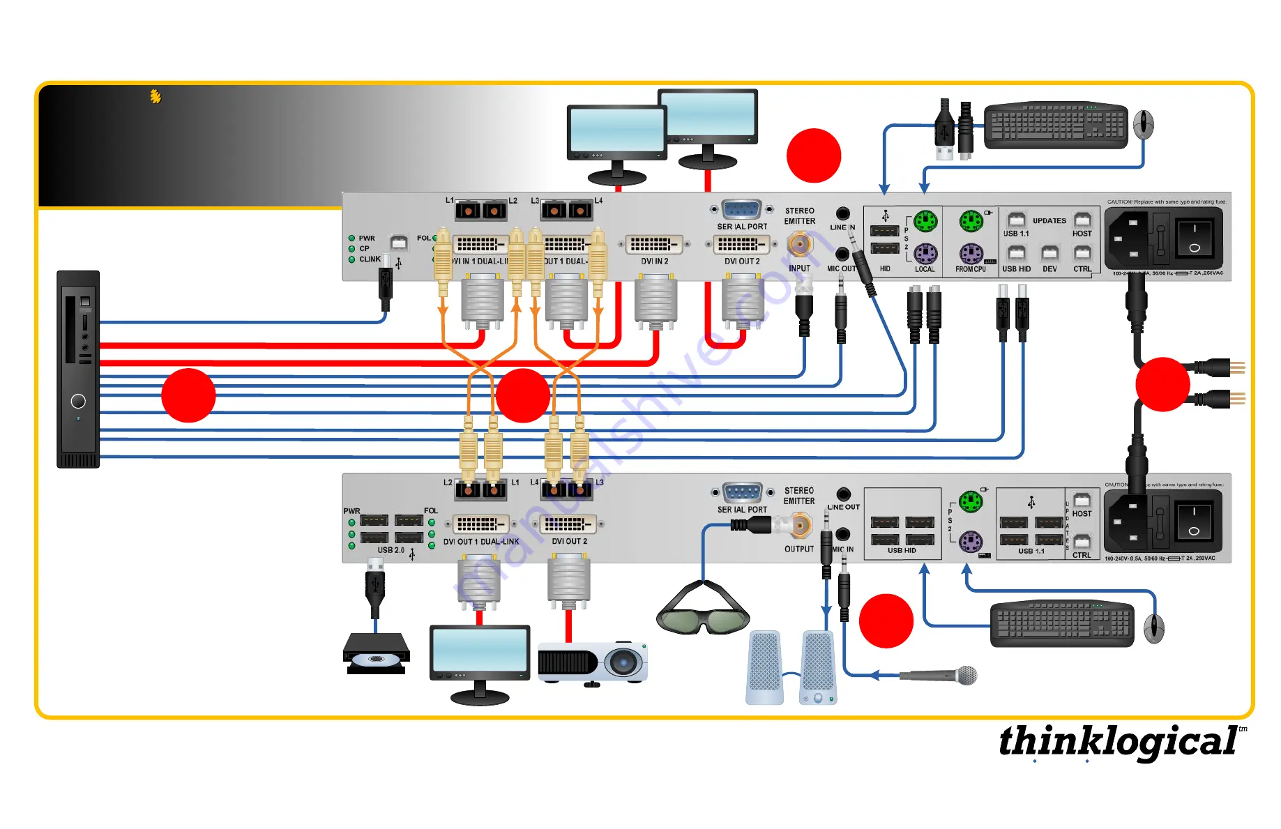
QUICK START GUIDE
STEP 5:
If desired, connect your
optional local keyboard &
mouse
by inserting the PS/2 or USB HID connectors into the
VelocityKVM Transmitter’s
local devices receptacles and
connect the
optional local DVI displays
to the Transmitter’s
DVI OUT Ports 1 & 2.
Ensure all system functions are
operating properly.
USB HID or PS2 Keyboard/Mouse
USB HID or PS2
Keyboard/Mouse
QUICK START GUIDE
Velocitykvm-28
Velocity
kvm-28
Multi-Mode Fiber Extension System
–
Dual- & Single-Link DVI, Two Display
Multi-Mode Fiber Extension System
–
Dual- & Single-Link DVI, Two Display
3
1
4
5
Local Dual-Link
DVI OUT 1
DVI OUT 2
USB 2.0 Option
Audio IN/OUT
Stereo 3-D
USB 2.0 Option
Audio OUT ►
Dual-Link DVI IN 1
STEP 1:
Connect the four Multi-Mode Fiber-Optic Cables
between the Transmitter and Receiver units (up to 1000
meters) as shown:
L1 to L1, L2 to L2, etc.
Audio
◄IN
PS/2 Keyboard
PS/2 Mouse
USB HID (Kybd/Mouse)
USB 1.1 (Kybd/Mouse)
Stereo Emitter IN
*
STEP 2:
Ensure that
the POWER ON/OFF
switch is in the OFF
position (0) on both the
Tx and Rx units.
Connect the supplied
AC Power Cords to
both units and plug
each into a standard
AC supply. Turn both
switches ON (1).
Dual-Link DVI
OUT 1
STEP 4:
Connect the DVI and KVM cables between the
Source CPU and the
VelocityKVM Transmitter
using the
cables supplied in KIT-000005-R. Ensure the CPU is turned
ON.
STEP 3:
Connect the destination DVI and KVM devices to
the
VelocityKVM Receiver
using standard cables. Ensure
the devices are turned ON.
2
VELOCITY-28_Manual_QSG
Source CPU
DVI IN 2
Fiber-Optic Cables:
L1: Data Tx to Rx and Video 1 Primary
L2: Data Rx to Tx
L3: Video 1 Secondary
L4: Video 2
STEP 2:
*
8
Extend Distribute Innovate
Summary of Contents for VelocityKVM-24
Page 12: ...12 Extend Distribute Innovate...


