Thinklogical DCS StudioPRO Product Manual Download Page 19

MAN-000018

13

REVISION A

3.5.

General Button Usage – DDC Select

The TX and RX units both have a button labeled DDC SELECT. When the data communications fibers
L1 and L2 are connected, either button will control the state of the DDC operation. Each press of the
button will advance the DDC state from PASS to DYNAMIC to STATIC and back to PASS (a fine-tip
pencil, such as a mechanical pencil, works best). When the units are disconnected, the DDC state of the
TX unit is the master and will be sent to the RX when data communications are restored. In PASS
through mode, the CPU communicates directly with the connected monitor for DDC information. In
DYNAMIC mode the DDC of the monitor is read from the receiver and stored in the transmitter. In
STATIC mode the DDC information in the transmitter is not changed regardless of changes made at the
receiver end.

There is also a default DDC table stored in the device. This table is suitable for use with many standard
PC monitors. If you wish to restore the default DDC table to the product and automatically place the
device into STATIC DDC mode, hold the button down for approximately 7 seconds or until you see the
DDC mode LED change to static mode.

3.5.1. Operation of the Thinklogical DDC Modes

DDC (Data Display Channel) is a VESA standard communications channel between a display adapter
and a video monitor. DDC data is stored in a monitor and describes the monitors characteristics (vendor
name, serial number, frequency range, analog or digital capabilities, etc.). DDC information is read from
the monitor by a video card in order for the video card to gather Extended Display Identification Data
(EDID) and provide video acceptable to the monitor.

Due to the Thinklogical TX emulating a monitor it must provide a DDC table to the video card in order for
the video card to provide images for transport. Some video cards are very un-forgiving of DDC data. An
un-forgiving video card will shut off video output if the DDC is not present at boot up (missing monitor),
hot-plugged or the DDC information does not match expected parameters (digital or analog). Some
video cards are very tolerant and will produce video output under many conditions. Due to the variability
of video card DDC handling, Thinklogical products provide all or a subset of the DDC support modes
detailed below.

3.5.1.1. Dynamic Mode

Dynamic DDC mode is the default and recommended mode of DDC operation. In this mode the RX will
read the DDC data from a monitor under 2 conditions; 1) power up and 2) if the monitor cable is removed
and reinstalled. The RX will only read the DDC information to RAM, it will not be stored on the RX.
Once the RX has validated the DDC data it informs the TX of a change in DDC information. Once
informed of a DDC change the TX reads the DDC information from the RX. If the DDC data read from
the RX is different than the DDC information stored in the TX non-volatile memory, the TX writes the new
DDC information to non-volatile memory on the TX that the video card can read. The TX then informs
the video card that the DDC information has changed so that the video card may read the DDC data and
act appropriately. In this mode the CPU may be booted up with the TX off or disconnected from the RX
since the TX non-volatile DDC memory can be read by the video card without TX power.

Summary of Contents for DCS StudioPRO

Page 1: ...000018 REVISION A DCS StudioPRO USB and Video Extender Product Manual Thinklogical Inc 100 Washington Street Milford Connecticut 06460 U S A Telephone 203 647 8700 Fax 203 783 9949 www thinklogical c...

Page 2: ......

Page 3: ...klogical a subsidiary of Logical Solutions Incorporated 100 Washington Street Milford Connecticut 06460 U S A Telephone 203 647 8700 All trademarks and service marks are property of their respective o...

Page 4: ...smitter 12 3 4 2 Receiver 12 3 5 General Button Usage DDC Select 13 3 5 1 Operation of the Thinklogical DDC Modes 13 4 Regulatory and Safety 15 4 1 Safety Requirements 15 4 1 1 Symbols Found on Produc...

Page 5: ...MAN 000018 iii REVISION A Appendix A Ordering Information 21 A 1 StudioPRO Extenders 21 A 2 Related Products DCS StudioPRO Matrix Switch 21 Appendix B Enclosure Dimensions 22...

Page 6: ......

Page 7: ...video connections External power is required for both the transmitter and receiver units and two universal power supplies are included Plug and play with no adjustments makes setting up the SPE fast a...

Page 8: ...ossible exposure to laser energy it is good practice to attach the fiber optic cables prior to applying power to the StudioPRO EXTENDER If the fiber optic cable should become disconnected DO NOT attem...

Page 9: ...necessary Supports USB 1 1 low speed full speed and USB 2 0 hi speed devices Uses standard duplex multi mode fiber optic cable LEDs provide link performance status Available with your choice of ST or...

Page 10: ...MAN 000018 4 REVISION A 2 2 1 Transmitter Figure 2 Front and Back Views of the SPE Transmitter Models 2 2 2 Receiver Figure 3 Front and Back Views of the SPE Receiver Models...

Page 11: ...ided and required 1 Dual Link Receiver DVI D female video input 1 Fiber connector data 2 Fiber connectors video 2 USB A connectors 4 Power connector AC adapter provided and required 1 Single Link Tran...

Page 12: ...cron or 62 5 micron Fiber Cable is either customer supplied or can be ordered from Thinklogical Operating Temperature and Humidity 0 to 50 C 32 to 122 F 5 to 95 RH non condensing Housing Dimensions in...

Page 13: ...FROM CPU SINGLE LINK POWER USB2 0 5VDC L3 L1 R L2 T POWER DVI TO DISPLAY SINGLE LINK Single Link DVI USB2 0 3 fibers SPE SL2 0 transmitter SPE SL2 0 receiver DVI single link Display USB2 0 DVD Keyboar...

Page 14: ...the Transmitter unit Plug that corresponding end of fiber into T L2 location labeled on the Receiver unit or StudioPRO 3 Plug fiber into R L3 location labeled on the Transmitter unit Plug that corresp...

Page 15: ...e length A fiber optic cable must be run between the location of the SPE Transmitter near your CPU or other DVI D video source and the SPE Receiver near the monitor projector etc The standard multi mo...

Page 16: ...to the fiber connector labeled L4 on the Receiver Figure 6 Proper Connection of Fiber Cable Shown Note When you connect the fibers THE FIBER CABLE SHOULD NOT BE CROSSED 3 3 2 Digital Video DVI D Inpu...

Page 17: ...should be able to connect to the USB Type A ports on the Receiver Figure 8 USB Type A Connector 3 3 6 AC Power Supply PWR 000022 R Quantity 2 Separate wall pack AC DC adapters part number PWR 000022 a...

Page 18: ...LED is ON solid green when a device is connected to the corresponding USB device port Video Single Link Version Only LED is ON solid green when a DVI signal is properly established Video SL Dual Link...

Page 19: ...o card in order for the video card to gather Extended Display Identification Data EDID and provide video acceptable to the monitor Due to the Thinklogical TX emulating a monitor it must provide a DDC...

Page 20: ...X non volatile DDC memory can be read by the video card without TX power 3 5 1 3 PassThru Mode PassThru DDC mode Pass Through mode gives the video card direct access to the monitor connected to the RX...

Page 21: ...4 digits for the year and 2 or 3 digits for a unique unit number This serial number is also found on the original shipping carton 4 1 3 Connection to the Product Connections and installation hardware...

Page 22: ...ealand This is a Class A product In a domestic environment this product may cause radio interference in which case the user may be required to take adequate measures 4 5 European Union 4 5 1 Declarati...

Page 23: ...e This equipment has been tested and found to comply with the limits for a Class A digital device pursuant to part 15 of the FCC Rules These limits are designed to provide reasonable protection agains...

Page 24: ...rique de la classe A respecte toutes les exigencies du R glement sur le mat rial brouilleur du Canada __________________________________________________________________________________ WARNING This i...

Page 25: ...www adobe com for a download 5 1 2 Email Thinklogical is staffed Monday through Friday from 8 30am to 5 30pm Eastern Time Zone We will try to respond to your email inquiries promptly use the followin...

Page 26: ...t time of purchase on most products Please refer to your product invoice for your products Warranty Terms Conditions 5 2 2 Return Authorization If for some reason you need to return your thinklogical...

Page 27: ...r Dual Link DVI USB 1 1 LC SPE DL1 1 STTX StudioPRO Transmitter Dual Link DVI USB 1 1 ST SPE DL1 1 SCTX StudioPRO Transmitter Dual Link DVI USB 1 1 SC SPE DL1 1 LCTX StudioPRO Transmitter Dual Link DV...

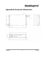
Page 28: ...MAN 000018 22 REVISION A Appendix B Enclosure Dimensions...

Reviews: