
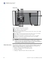

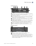
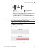


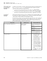
Lambda SC back panel
2
3
5
4
7
6
8
1
1
Fuse Label—Information found here includes the instrument model number, appropriate
supply voltage, and the type of fuse required for the supply voltage.
2
Power Switch—Used with power socket to turn power on and off to the Lambda SC and the
attached Lambda LS light source.
3
Fuse—Fuse compartment contains the supply voltage fuse and an extra fuse. Replace
blown fuses with a fuse of the appropriate value as given on the fuse label. Mains fuse: 5 x
20-mm glass tube, T1.0A 250 V IEC 60127-2 Sheet III.
4
Line Power—Power socket is used to connect the supplied power cord to the Lambda SC.
5
Smart
Shutter
™
port—9-pin DSUB male connector used to link the Lambda SC with the
Lambda LS
Smart
Shutter
™
light source.
6
TTL Input and Output—Two BNC receptacles for TTL control of the connected Lambda LS
Smart
Shutter
™
light source. TTL IN is connected to the back panel of the GeneTitan
™
Scanner. TTL OUT is not used in the GeneTitan
™
Scanner System configuration.
7
Serial port—9-pin DSUB female receptacle that establishes an RS-232 serial interface
between the Lambda SC and a host computer using the provided cable.
8
USB port—USB B-type port. The GeneTitan
™
Scanner System does not use this port.
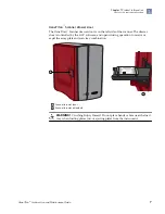
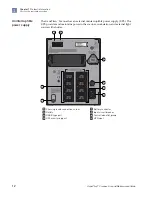
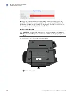
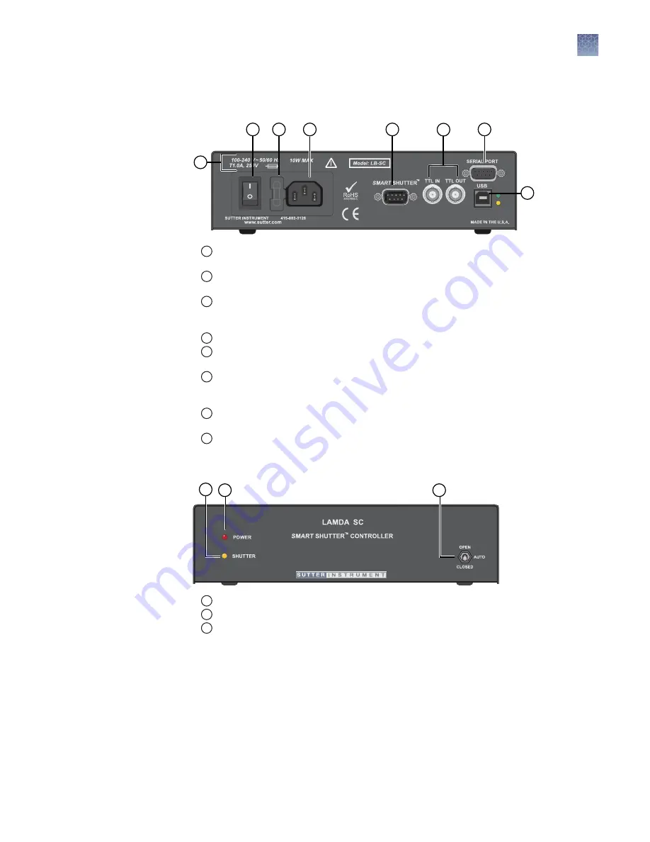
Lambda SC front panel
2
1
3
1
Shutter Light—This lamp is lit while the
Smart
Shutter
™
is in the open state.
2
Power Light—This lamp is lit while the controller is powered on.
3
Manual Shutter Control Switch (Open Auto Closed)—This 3-position switch manually
opens or closes the
Smart
Shutter
™
, overriding programmed operation or external control
(TTL signaling and/or remote host computer connected via RS-232 Serial or USB).
The manual shutter control switch middle position (labeled AUTO) places the Lambda SC
controller into control of its programming under TTL control or under the control of an
externally connected host computer.
Chapter 1
Product information
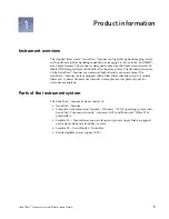
Parts of the instrument system
1
GeneTitan
™
Scanner Use and Maintenance Guide
11


