9
Fig. 6: Suggested method to accommodate vent connector passage through a wall composed of a combustible material.
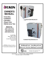
Fig. 7: Alternate constructions that allow reduced clearances to combustible materials.
REDUCTION OF CLEARANCES WITH SPECIFIED FORMS OF PROTECTION:
Type of protection applied to and covering all surfaces of combustible material within the distance
specified as the required clearance with no protection unless otherwise noted, all dimensions in inches,
refer to Fig. 7.
18 inches
9 inches
6 inches
Sides &
Sides &
Sides &
Required clearance with no protection from the appliance or
chimney connector is:
Above Rear
Above Rear
Rear
a. 3-1/2" thick masonry wall without ventilation air space….
-- 12
-- 6
-- 5
b. 1/2" insulation board over 1" glass fiber or mineral wool batts…
12 9
6 5
4 3
c. 0.024(24 gauge) sheet metal over 1" glass fiber or mineral
wool batts reinforced with wire on rear face with ventilated air
space…
9 6
5 3
3 3
d. 3- 1/2" thick masonry wall with ventilation air space..
-- 6
-- 6
-- 6
e. 0.024 (24 gauge) sheet metal with ventilated air space.
9 6
5 3
3 2
f. 1/2" thick insulation board with ventilation air space..
9 6
5 3
3 3
g. 0.024 ( 24 gauge) sheet metal with ventilated air space over
0.024 (24 gauge) sheet metal with ventilated air space….
9 6
5 3
3 3
h. 1" glass fiber or mineral wool batts sandwiched between two
sheets 0.024 (24 gauge) sheet metal with ventilated air space
9 6
5 3
3 3
A. Equal the required clearance with no protection.
B. Equals the reduced clearance permitted in accordance with the preceding clearance chart.
C. The protection applied to the construction that covers the combustible material should extend far enough
in each direction to make C equal to A.
Summary of Contents for OD6FA072D48B
Page 5: ...2...
Page 61: ...58 VIII Sequence of Operations Flow Chart...
Page 62: ...59...
Page 63: ...60 IX Trouble Shooting Flow Chart...
Page 64: ...61...
Page 65: ...62...
Page 66: ...63...
Page 67: ...64...
Page 69: ...66 Appendix A Replacement Parts Replacement Parts for OD6F 072D...
Page 70: ...67...
Page 71: ...68 Replacement Parts for OD6R 072D...
Page 72: ...69...
Page 73: ...70 Appendix B Wiring Diagrams OD6 A072D48 PSC Wiring Diagram...
Page 74: ...71 OD6 A072DV5 ECM Wiring Diagram...
Page 75: ...72 OD6 X072DV5 ECM 2 Stage Wiring Diagram...
Page 76: ...73...