Models 3940 and 3949_________________________________________________________________Start-Up and Operation
3 -3
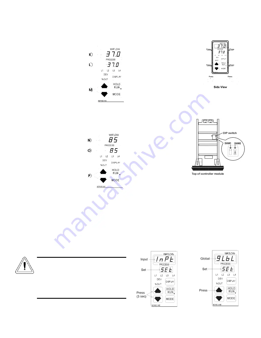
3.2 Setting the Incubator’s Operating Temperature
(Figure 3-5)
The Watlow temperature
controller’s upper numerical
display shows the actual temperature
inside the incubator chamber. The
lower display shows the temperature
setpoint.
Changing the Setpoint
To raise or lower the set-
point, press the up or down
arrow. Temperatures are set in .1°C
increments.
3.3 Setting the Incubator’s Operating Humidity
(Figure 3-6)
The Watlow humidity
controller’s upper numerical
display shows the actual humidity inside
the incubator. The lower display shows
the humidity setpoint.
To raise the setpoint, press the
up or down arrows. Humidity is set
in one percent increments.
3.4 Programming the controllers
The Watlow temperature and humidity controllers have
been set at the factory to operate the incubator within the speci-
fications listed in Section 6 of this manual. Reference copies of
the Watlow configuration records are included at the end of
Section 2 of this manual.
To prevent tampering, mechanical and software lockouts
are employed in the system. These lockouts must only be
removed by persons skilled in configuring controller software.
Making program changes to either the tempera-
ture or humidity controllers will seriously alter the
performance of the incubator and therefore must
be made only by qualified persons. The con-
trollers should not be re-configured without first
consulting Thermo Forma Service Department, at
1-888-213-1790.
a. Removing the mechanical lockout
Make sure the unit is turned
off.
Wearing a grounding wrist
strap or maintaining constant con-
tact with the metal cabinet, press
in the four locking tabs on the
frame of the Temperature con-
troller. There are two tabs on
either side as shown in the front
and side views in Figure 3-7.
When all tabs are unlocked, pull
the controller module out of its frame.
Looking at the top of the module, locate the red DIP switch
indicated in Figure 3-8. With a fingernail or small screwdriver,
turn off SW #2 by moving the
white toggle down or towards
the front of the module. (SW#2
is the top switch when looking
at the module from the right
side.)
Very carefully, replace the
module into its frame and press
firmly on the top and bottom of
the bezel until all four locking
tabs “click” into place.
b. Removing the Software Lockout
Press the up arrow and down arrow keys at the same time
and hold them for about three seconds. The words “inpt”
(input) and “set” will appear in the top and bottom displays.
(Figure 3-9) If numbers in the bottom display begin to scroll up
or down, the keys have not been pressed simultaneously. Try
again.
Press the up arrow until “gLbL” (global) appears in the
upper display. The word “set” will remain in the lower display.
(Refer to Figure 3-10)
K L
M
Figure 3-5
N O
P
Figure 3-6
Figure 3-7
Figure 3-8
Figure 3-9
Figure 3-10


