background image


10 

CLEANING AND MAINTENANCE 


Refer to following table for periodical maintenance and cleaning 

Part of the stove 

Every two days 

Every 60-90 days 

End of season by 

service technician 

Fire pot 


Fire pot housing 


Ash tray 


Front glass 


Heat exchanger 


Lower compartment     

(smoke chamber) 


Flue pipe / connection 


Electro-mechanical 

components 


Thermostat / sensor 

connections 


Fibre rope on front door 


10.1. Cleaning to be performed every 2 days by the user 
 

Fire Pot 

Remove the burning  pot  from  its compartment and free the holes using the brush  supplied 

with the stove or an appropriate tool.  If the pellets in the hopper finish, unburned pellets may 

accumulate in the burning pot, you can also use vacuum cleaner for unburnt pellets removal. 

Always empty the residue in the burning pot before starting-up. 


Fire pot housing

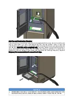
Clean the fire pot housing, preferably using a vacuum cleaner.  

Summary of Contents for ASTRA

Page 1: ...A S T R A Installation and User Manual 2021 R02 Astra_Micronova v2 ...

Page 2: ...convey in your home we advise you to read this manual carefully before starting up the product for the first time CARE OF THE MANUAL AND HOW TO CONSULT IT Take care of this manual and keep it in an easily accessible place Should the manual be misplaced or ruined request a copy from your retailer or directly from the authorised Technical Assistance Department ...

Page 3: ......

Page 4: ...rm warranty refers to the free of charge replacement or repairs of parts acknowledged to be faulty due to manufacturing defects Furthermore in order for the guarantee to be valid the product must be installed and calibrated by qualified personnel Installations that do not meet the current standards improper use and lack of maintenance as expected by the manufacturer void the product warranty The w...

Page 5: ...lt has been noticed In case of a boiler hydro stove any corrosion incrustations or breakages caused by water flow condensation lack of water in the system mud or limescale deposits Inefficiency of chimneys flues or parts of the system affecting the appliance Failure to have the annual product maintenance performed by an authorised technician or qualified personnel will result in the loss of the wa...

Page 6: ...TEM Switch the product off in the event of a fault or malfunctioning Accumulated unburned pellets in the burner fire pot after each failed start up must be removed before starting up again Do not wash the product with water The water could get inside the unit and damage the electrical insulation and cause electric shocks Do not climb on or lean on the product INSTALL THE PRODUCT IN ROOMS THAT ARE ...

Page 7: ...product defect 4 MAIN PARTS AND SPECIFICATIONS 1 User interface and command display 13 STB 2 Fuel loading cover 14 PCB main controller 3 Fuel loading grid 15 Feeding screw 4 Combustion chamber protective board 16 Room air ventilation fan 5 Front door 17 Combustion fan 6 Ceramic glass inspection window 18 Exhaust outlet pipe 7 Smokehood section 19 Combustion air inlet pipe 8 Burning pot 20 Igniter ...

Page 8: ......

Page 9: ......

Page 10: ...th 230V 50 Hz power supply with an EC compliant earth system Operating environment must ensure the following regulations unless any local regulation in force request different conditions The volume of the room where the product is installed should be no less than 15 m3 Air must enter through permanent openings made in the walls near the product that reach outwards with a minimum section of 80 cm2 ...

Page 11: ...in the room Observe the distances from flammable or heat sensitive objects sofas furniture wood panelling etc as specified below If particularly delicate objects are present such as furniture curtains or sofas increase the stove clearance accordingly A B If the floor is made of combustible material it is recommended to use protection made of non combustible material steel glass that also protects ...

Page 12: ...category T200 or higher if required by the smoke temperature of the appliance and P1 type airtight All 90 angles max 3 in the smoke exhaust duct must be preferably fitted with the relative T fittings with inspection hole It is strictly forbidden to fit a mesh at the end of the exhaust pipe as it could cause the product to malfunction due to clogging It is forbidden to use counter sloping pipes The...

Page 13: ...c it is advisable to fit a stainless steel pipe of suitable diameter throughout the length of the chimney right to the top The minimum internal dimensions of the external duct must be 10x10 cm or 10 cm in diameter and must not exceed 20x20 cm or 20 cm in diameter Only stainless steel insulated double wall pipes must be used which are smooth on the inside and fixed to the wall Flexible stainless st...

Page 14: ...let section B of not less than twice that of the flue A the part of the chimney that emerges from the roof or remains in contact with the outside e g in the case of a flat roof must be covered with brick or tile elements and in any case well insulated it must be built in such a way as to prevent the penetration of rain snow and foreign matter into the flue and to ensure that in the event of winds ...

Page 15: ...rical installation must be carried out by a qualified technician only Before performing connections or any operation on the electrical parts always disconnect the power supply and make sure it cannot be accidentally reconnected Please note that the stove electrical power line must be fitted with a bipolar switch with a contact gap greater than 3 mm easy to access in order to make any maintenance o...

Page 16: ...y lifting the cover on the upper part of the product Slowly pour the pellets into the hopper Be careful as the cover could become very hot No fuel other than pellets in compliance with above mentioned specifications is to be inserted into the hopper WARNING Do not allow sawdust to accumulate on the bottom of the hopper Do not leave leftover pellets on top of the stove as they could catch fire 7 3 ...

Page 17: ... use of the console What are the Buttons for Button Description Mode Action 1 Decrease Temperature SET TEMPERATURE Decrease the value of SET room temperature PROGRAMMING Decrease the selected parameter SET POWER Decrease the power value 2 Increase temperature SET TEMPERATURE Increase the value of SET room temperature PROGRAMMING Increase the selected value SET POWER Increase the power value 3 ON O...

Page 18: ...ew seconds Once turned on the display shows Start and the ON OFF LED will flash The stove now enters a state of pre heating during which the glow plug and the smoke extraction fan both turn on Any problems during the turning on phase will be shown on the display and the stove s alarm will sound 8 2 2 Pellet Loading After about 1 minute the pellet loading phase will begin the display will show Load...

Page 19: ...uring this phase will stop the stove and an error message will show 8 2 4 Working Mode After flue temperature has reached and surpassed the level and remained so for the time adjusted by manufacturer the stove will enter the WORK mode which is its normal function The display will show Work and the ON OFF LED will be on Power can be adjusted by pressing the P2 key and ambient temperature by pressin...

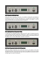
Page 20: ...ing simply press the P1 button The display shows the room temperature set SET Temperature Pressing P1 to reduce and P2 to increase will change this number After about 5 seconds the number entered is memorized by stove and the display returns to normal Alternatively to exit you can press P3 8 2 7 Room Temperature Reaches the Set Temperature When the ambient temperature has reached the level set the...

Page 21: ... standby followed by the minutes remaining At the end of the time period set by manufacturer the display will show Wait Cooling In this state the feed screw and its LED will turn off the air ventilator fan will turn off once it reaches the threshold and the ON OFF LED will flash When the temperature of the air reaches the threshold the stove enters stand by mode and the display will show Stop eco ...

Page 22: ...ellet installation chimney conditions draft and air entrance to burner If at the end of combustion periods there is too much pellet in the fire pot or if the color of flame turns to red or if the stove has difficulty to fire up it means that some combustion parameters should be re adjusted according to the real conditons in the field For this purpose please refer to pellet type or chimney type adj...

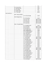
Page 23: ...day prog 1 on off 06 Wednesday prog 1 on off 07 Thursday prog 1 on off 08 Friday prog 1 on off 09 Saturday prog 1 on off 10 Sunday prog 1 on off 11 Start prog 2 OFF 0 23 50 12 Stop prog 2 OFF 0 23 50 13 Monday prog 2 on off 14 Tuesday prog 2 on off 15 Wednesday prog 2 on off 16 Thursday prog 2 on off 17 Friday prog 2 on off 18 Saturday prog 2 on off 19 Sunday prog 2 on off 20 Start prog 3 OFF 0 23...

Page 24: ...M3 Select Language 01 Italiano set 02 English set 03 Francais set 04 Deutsch set M4 Stand by Mode 01 Stand by on off M5 Buzzer Mode 01 Buzzer Mode on off M6 Initial Load 01 Initial Load 90 M7 Stove State 01 Stove State 01 Auger state info 02 T minutes info 03 Thermostat state info 04 Flue State info 05 Smoke extractor rotating status rpm info M8 Technical Setting 01 Access Key set M9 Escape 01 Esc...

Page 25: ...o go up To confirm press P3 8 3 3 Menu M2 Set Timer Program Submenu M2 1 Enable Chrono The menu shown on the M2 set chrono display allows you to enable or disable all of the functions of the chrono thermostat in on ego To enable them press P3 and then either P1 or P2 for On or Off respectively Confirm by pressing P3 Submenu M2 2 Program day Select the menu M2 2 program day and press P3 to see and ...

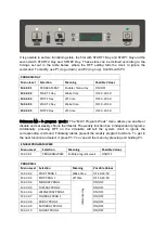
Page 26: ...u allows you enable or disable and set weekly chrono thermostat The weekly function has 4 independent programs Additionally pressing OFF on the timetable will tell the system clock to ignore the corresponding command Following tables present the weekly program functions To get to the next function and select it press P3 You can exit the menu by pressing and holding P3 ENABLE PROGRAM WEEK Menu Leve...

Page 27: ...Y PROG 3 reference day ON OFF M2 3 23 TUESDAY PROG 3 ON OFF M2 3 24 WEDNESDAY PROG 3 ON OFF M2 3 25 THURDAY PROG 3 ON OFF M2 3 26 FRIDAY PROG 3 ON OFF M2 3 27 SATURDAY PROG 3 ON OFF M2 3 28 SUNDAY PROG 3 ON OFF PROGRAM 4 Menu Level Selection Meaning Possible Values M2 3 29 START PROG 1 Wake time OFF 0 23 50 M2 3 30 STOP PROG 1 off time OFF 0 23 50 M2 3 31 MONDAY PROG 1 reference day ON OFF M2 3 32...

Page 28: ... that the stove will function on Saturday while Start 2 weekend and Stop 2 weekend will set the operating times for Sunday 8 3 4 Menu M3 Language selection Allows you to set the language from those available To move to the next language press P2 to go up and to go back press P1 To confirm press P3 8 3 5 Menu M4 Stand by Allows you to enable or disable Standby mode Once you have selected the M4 men...

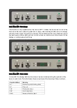
Page 29: ... maximum speed the feed screw and its LED will turn on and remain on until the end of the shown on the display or until you press the P3 key 8 3 8 Menu M7 Stove status In menu M7 the display will show the status of several variables during the operation of the stove in work mode The table below shows an example of the meaning of these numbers Visualized Status Meaning 3 1 Feed screw pellet loading...

Page 30: ...L 6 NO PELLET Thermal safety over temperature AL 7 ALAR AL 7 SAFETY THERMAL Depression absence AL 8 ALAR AL 8 FAILURE DEPRESS Every alarm causes the stove to immediately shut down State of alarm occurs after reaching a time defined by manufacturer except for the blackout alarm all alarms re activated after a period of time And can be reset by pressing and holding P3 key For security reasons each t...

Page 31: ... on and the display showing Al 7 alar al 7 safety thermal The stove will turn itself off 8 4 8 Depression failure alarm The alarm will sound when the air pressure switch reaches a pressure reading lower than the trigger threshold The pressure switch will turn off the feed screw and the controls will indicate a state of alarm with the alarm LED on while the display will read Al 8 alar al 8 failure ...

Page 32: ... of the product Other fuses that protect the electronic boards are found on the latter BACK FLAME FIRE SAFETY A manual reset type safety thermostat protects the stove from any flame back flow to fuel hopper SMOKE FAN If the fan stops the electronic board promptly shuts off the pellets supply and an alarm message is displayed GEAR MOTOR If the gear motor stops the stove will continue to run until t...

Page 33: ... o Thermostat sensor connections o Fibre rope on front door o 10 1 Cleaning to be performed every 2 days by the user Fire Pot Remove the burning pot from its compartment and free the holes using the brush supplied with the stove or an appropriate tool If the pellets in the hopper finish unburned pellets may accumulate in the burning pot you can also use vacuum cleaner for unburnt pellets removal A...

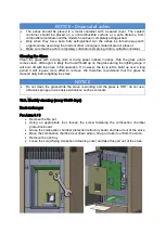
Page 34: ... just sweep this ash into ash pan Only if the ash is completely cold a vacuum cleaner can be used to remove it Use a drum type vacuum cleaner that is suitable for picking up particles of a certain size Experience and the quality of the pellets will determine the cleaning frequency required However it is recommended not to exceed 2 or 3 days NOTICE REMEMBER THAT ONLY A CORRECTLY POSITIONED AND CLEA...

Page 35: ...on the glass during the lighting stage it will burn off with the stove in full operation If however the tar is left to build up over a long period it will require more effort to remove We therefore recommend that the glass be cleaned daily before lighting the stove NOTICE Do not clean the glass while the stove is working and the glass is HOT do not use abrasive sponge and corrosive substance such ...

Page 36: ...amber rear sheet plate a bit up ad take it out from the stove Remove the ash tray Loose the screw fixing smokehood cleaning cover and take this part out of the stove Now clean all surfaces around the combustion chamber with supplied original brush with plastic handle Move all deposits down into the ash compartment under combustion chamber Remove the deposited ash and combustion products including ...

Page 37: ...switches Check the tightness and state of the gaskets seals of the glass door Check the seal and tightness of the joints on flue Carry out all maintenance and checks required for correct operation and adaptation to safety regulations Light the stove in accordance with instructions given in the paragraph NOTICE All cleaning and maintenance must be carried out with the power cable disconnected from ...

Page 38: ...of a vacuum cleaner with an extension 11 ALARMS AND TROUBLESHOOTING If a problem is detected during operation the stove will intervene and alert you by turning on the alarm LED and making a noise The following alarms could sound Origin of Alarm Display Black out AL 1 OUT Flue gas temperature probe AL 2 FUME PROBE Flue gas over temperature AL 3 HOT FUME Flue encoder damaged AL 4 FAN FAILURE Ignitio...

Page 39: ...t or chimney Please be sure that the air input of the stove is not blocked by any material To check origin of problem and solve it please refer to the following steps 1 Perform a cleaning explained on section 10 1 every 2 days 2 Fire up the stove and watch until the stove burns up Check for pellet level on a few stages After preloading of pellets and starting to load pellet wait fire how high is t...

Page 40: ... Display M8 1 Settings Factory M8 2 Set general M8 3 Type pellet M8 4 Type chimney M8 5 Data bank M8 6 Test outputs M8 7 Reset part time M8 8 Reset alarm M8 9 Counter memories M8 A Escape Within the submenus by pressing P3 repeatedly you can scroll through all the configuration parameters To modify a parameter press P1 to decrease or P2 to increase Confirm by pressing P3 The system will memorize t...

Page 41: ...Chimney Type Optimization This optimization has 2 steps First ignition fan speed must be optimized Since the problem is pellet level is increasing on the burning pot fan speed must be increased before work phase From M8 1 Settings Factory menu you can increase Pr16 and Pr17 parameters to adjust fan speed on needed functioning stages Please note the original and the adjusted parameters Second use t...

Page 42: ...ricity Sensor wires sensors and keyboard wires must be mounted so that they cannot be accessed without disassembling the combustion device Earth connection must be connected to the controller and to the metal part of the combustion device Some of the wires carry dangerous voltages Disconnect the controller from the mains power supply prior to any service or mounting operation Do not exchange high ...

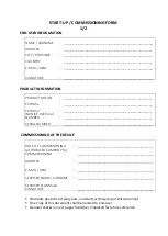
Page 43: ...____________________________________ INVOICE DATE and NUMBER _________________________________________________ SERIAL NUMBER _________________________________________________ COMMISSIONING OF THE DEVICE DATE OF COMMISSIONING __________________________________________ AUTHORIZED COMPANY for COMMISSIONING __________________________________________ ADDRESS __________________________________________ E...

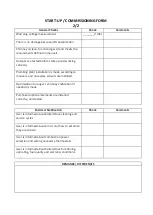
Page 44: ...o manuals and necessary sensors are installed Optimization for auger chimney calibration if needed is made Purchased optional elements are installed correctly and tested End User Notification Check Comments User is informed about boiler stove cleaning and service cycles User is informed about errors and how to act when they are shown User is informed about combustion power selection and setting ne...

Reviews: