INSTALLATION
3-8
Manual 0-2746
B. Machine Systems (Unshielded Leads)
WARNING
Disconnect primary power at the source before as-
sembling or disassembling the power supply, torch
parts, or torch and leads assemblies.
1.
Turn the screw latch securing the front access panel
to the power supply front panel.
2.
Lift the access panel for access to the torch bulk-
head panel.
3.
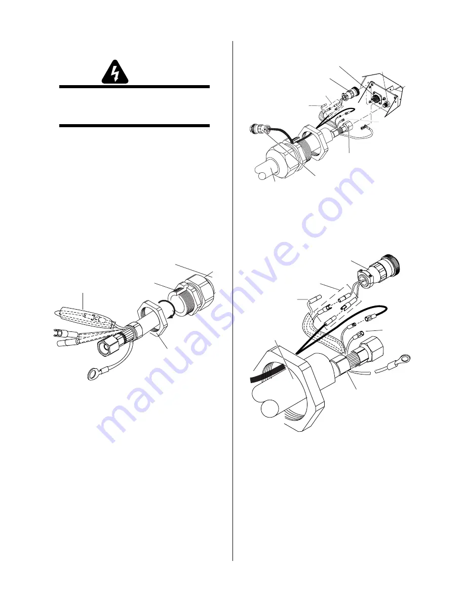
Remove the retaining nut from the Strain Relief.
4.
The torch leads includes a pair of wires covered
with an insulator and joined with mating connec-
tors. Remove the tie wrap, remove the insulator,
and disconnect the wires.
Strain Relief
Nut
Strain Relief
Torch Leads
Assembly
A-03609
Remove Tie Wrap,
Remove Insulator,
Disconnect Wires
Figure 3-13 Strain Relief Nut Removal
5.
The Power Supply Adapter must be installed as
follows:
a. Inside the Power Supply Bulkhead area, route
the wires on the Adapter through the Strain Re-
lief Nut.
b. Continue routing the wires out the hole in the
front panel of the Power Supply.
c. Feed the end of the torch lead and the Strain
Relief into the hole in the unit while routing
the wire into the notch of the Strain Relief.
d. Tighten the Strain Relief Nut to secure the
Strain Relief to the Power Supply.
Power Supply Adapter
Pilot Lead
Torch Lead
Assembly
Negative/Plasma
Lead
Adapter Connector
Negative/Plasma
Lead Connection
A-03612
Control Circuit
Connectors
Remote
Pendant Adapter
Open
Open
Figure 3-14A Torch Lead Connections
A-03611
Pilot Lead
Torch Lead
Assembly
Negative/Plasma
Lead
Control Circuit
Connectors
Open
Open
Power Supply Adapter
Figure 3-14B Torch Lead Connection Detail
6.
Connect the torch Negative / Plasma Lead to the
bulkhead connection inside the Power Supply.
7.
Connect the Control Circuit Connectors to the mat-
ing connectors on the Power Supply Adapter. Two
wires from the torch leads will remain open.
8.
Remove the top nut and washer from the Pilot
Stud.
Summary of Contents for PakMaster 75XL Plus
Page 2: ......
Page 6: ......
Page 12: ...GENERAL INFORMATION 1 6 May 14 2002...
Page 26: ...INSTALLATION 3 12 Manual 0 2746...
Page 45: ...Manual 0 2746 A 5 APPENDIX This page left blank...
Page 46: ...APPENDIX A 6 Manual 0 2746 A 02503 APPENDIX 5 SYSTEM SCHEMATIC...
Page 47: ...Manual 0 2746 A 7 APPENDIX A 02503...
Page 48: ......


