


Manual 0-2747
4-13
TROUBLESHOOTING
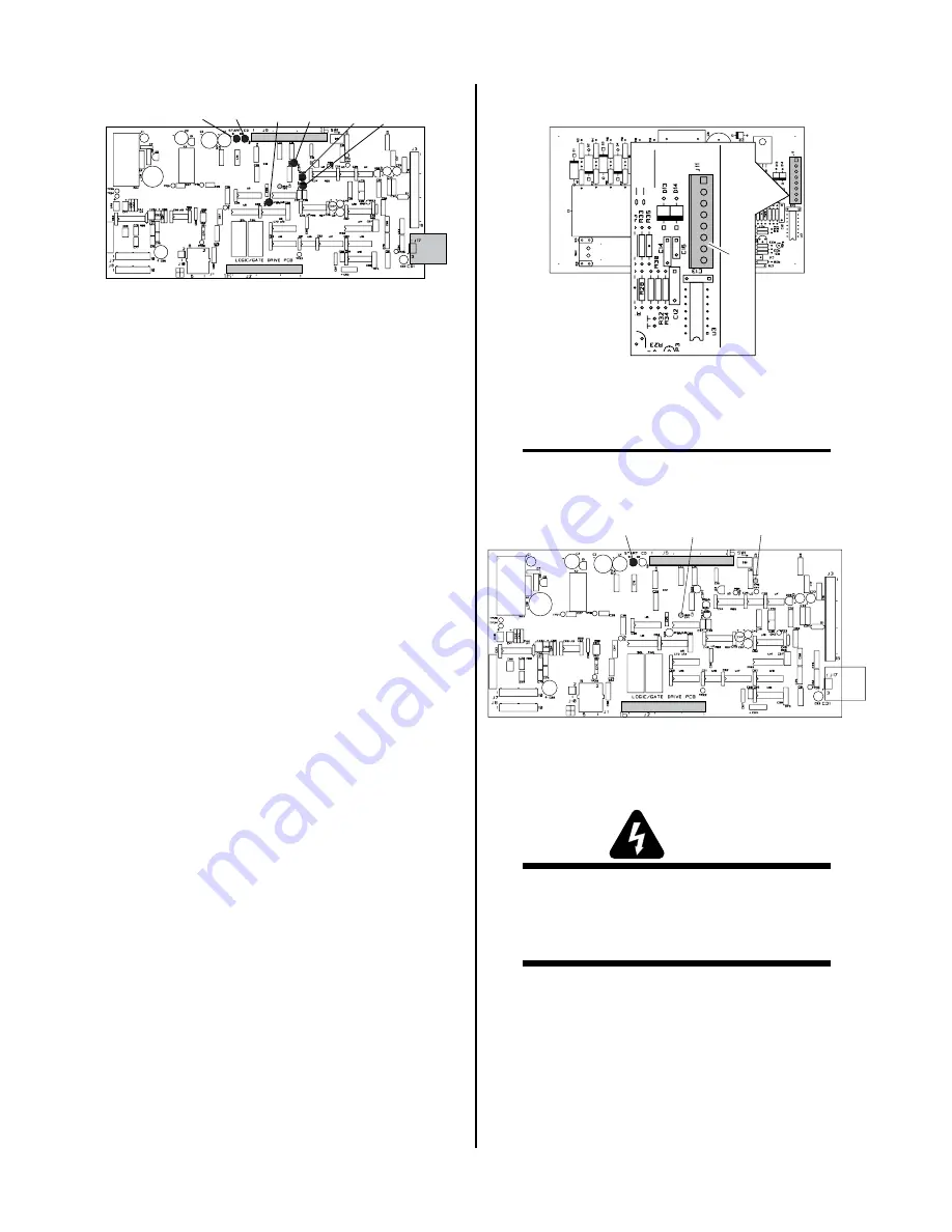
A-02550
Logic/Gate PC Board
D1
D45
D39
D36
D20
D2
1. No DC Output
An open circuit voltage of approximately 280 to 325
vdc (depending on input power selected) is produced
when switching transistors in the FET/Heatsink As-
semblies are turned ON by a PWM (Pulse Width
Modulation) Enable signal from the Logic/Gate PC
Board. A circuit on the Logic/Gate PC Board moni-
tors the output voltage. When the output voltage
drops below 60 vdc, indicating a problem exists, the
Logic/Gate PC Board sends a signal which turns OFF
the PWM Enable signal to the Logic/Gate PC Board.
Because this happens in less than 50 milliseconds, it
is not easy to take voltage readings to find the source
of the problem.
When the unit is at “idle” the AC OK indicator on
Front Access Panel should be ON. The Start indica-
tor, D1, turns ON when the torch switch is pressed.
At this point the gas begins to flow. When the preflow
time is over the PWM Enable signal is given PWM
turns on, and the DC indicator at the front panel turns
ON. When the PCR Drive/Pilot On indicator D39
turns ON.
If the PWM Enable indicator, D45, does not come ON
then replace the Logic/Gate PCB.
If the PWM Enable indicator, D45, turns ON then OFF
immediately, the following test should be performed:
a. Disconnect J11 from the CD PC Board to dis-
able the CD signal.
A-01202
J11
CD PC Board
b. Connect a jumper between TP1 and TP8 of the
Logic/Gate PC Board.
NOTE
Before pressing the trigger, make sure no faults were
found on the Pilot Board and in the torch.
A-02552
Logic/Gate PC Board
TP8
D1
TP1
This will cause the gas to flow continuously and
the DC indicator on the front panel to turn ON.
WARNING
Connector J11 on the CD PC Board must be dis-
connected to prevent electrical damage to measur-
ing equipment when testing the open circuit volt-
age (OCV).
c. Press and hold the hand torch switch (Logic/
Gate PC Board Start indicator, D1 turns ON).
After 2 seconds D45 (Logic/Gate PCB) turns
on. If D45 does not turn on, replace Logic/
Gate PCB.
d. Measure open circuit voltage between E29 (+)
to E7 (-) at the Pilot Output PC Board.
Summary of Contents for Pak Master 75XL Plus
Page 2: ......
Page 6: ......
Page 16: ...INTRODUCTION 2 2 Manual 0 2747...
Page 49: ...Manual 0 2747 6 5 REPLACEMENT PARTS This page left blank...
Page 71: ...Manual 0 2747 A 15 APPENDIX Notes...
Page 72: ...APPENDIX A 16 Manual 0 2747 APPENDIX 12 SYSTEM SCHEMATIC A 02503...
Page 73: ...Manual 0 2747 A 17 APPENDIX A 02503...
Page 74: ......


