background image

A40i, A60i

Manual 0-5466  

OPERATION 

4T-15

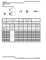
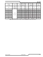
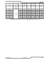
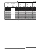
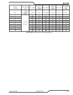
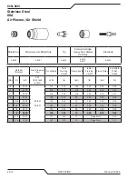
Material 

Thickness

Gas Pressure 

(Air)

Arc Voltage

Torch 

Working 

Height

Travel Speed

Initial 

Piercing 

Height

Pierce Delay

Kerf Width  

@ Rec. 

Speed

(mm)

 Bar 

(torch lead 

length)

Volts

(mm)

(mm/min)

(mm)

(sec)

(mm)

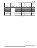
1.0

4.8 (7.6m) 


5.2 (15.2m)

95

4.1

7620

4.1

0.0

1.5

2.0

104

4.1

3500

4.1

0.2

1.6

3.0

115

4.1

2350

4.6

0.3

1.7

4.0

113

4.6

2170

4.6

0.4

1.7

5.0

118

4.6

1740

4.6

0.5

1.8

6.0

125

4.6

1015

4.6

0.8

1.9

8.0

139

4.6

500

Edge Start

2.0

10.0

153

4.6

180

Edge Start

2.2

BOLD TYPE

 indicates maximum piercing parameters.  

BOLD ITALIC

 indicates edge starts only.

Summary of Contents for A40i

Page 1: ...208 480V thermal dynamics com 40 380 415V 60 Revision AB Issue Date 7 3 2018 Manual No 0 5466 OPERATING MANUAL A40i A60i PLASMA CUTTING SYSTEM...

Page 2: ...ncern Therefore please take the time to read the entire manual especially the Safety Precautions They will help you to avoid potential hazards that may exist when working with this product YOU ARE IN...

Page 3: ...other cause For Material Print Specifications refer to document 47x1909 Original Publication Date 16 November 2017 Revision Date 7 3 18 Record the following information for Warranty purposes Where Pur...

Page 4: ...eof contained in this manual and ac companying labels and or inserts when installed operated maintained and repaired in accordance with the instructions provided This equipment must be checked periodi...

Page 5: ...ISATEUR Cet quipement fonctionnera conform ment la description contenue dans ce manuel les tiquettes d accompagnement et ou les feuillets d information condition d tre install utilis entretenu et r pa...

Page 6: ...This Page Intentionally Blank...

Page 7: ...26 1888 FAX 01 603 298 7402 The following harmonised standard in force within the EEA has been used in the design IEC EN 60974 1 2012 Arc Welding Equipment Part 1 Welding power sources IEC EN 60974 10...

Page 8: ...This Page Intentionally Blank...

Page 9: ...tion 2T 1 2T 03 Specifications 2T 1 2T 04 Quick ConnectionTorch 2T 2 2T 05 Options And Accessories 2T 2 2T 06 Introduction to Plasma 2T 2 SECTION 3 SYSTEM INSTALLATION 3 1 3 01 Unpacking 3 1 3 02 Lift...

Page 10: ...SERVICE 5 1 5 01 General Maintenance 5 1 5 02 Maintenance Schedule 5 2 5 03 Common Faults 5 3 5 04 Fault Indicator 5 4 5 05 BasicTroubleshooting Guide 5 5 5 06 Power Supply Basic Parts Replacement 5...

Page 11: ...CH PIN OUT DIAGRAMS A 3 APPENDIX 4 TORCH CONNECTION DIAGRAMS A 4 APPENDIX 5 CNC CABLE COLOR CODE A 5 APPENDIX 6 AUTOMATION INTERFACE A 6 APPENDIX 7 SYSTEM SCHEMATIC 208 480V 1PHASE A 8 APPENDIX 8 SYST...

Page 12: ...TABLE OF CONTENTS This Page Intentionally Blank...

Page 13: ...egorized as follows NOTE An operation procedure or background information which requires additional emphasis or is helpful in efficient opera tion of the system CAUTION A procedure which if not proper...

Page 14: ...une explosion ou un incendie 1 1 Ne pas couper pr s des mati res inflammables 1 2 Un extincteur doit tre proximit et pr t tre utilis 1 3 Ne pas utiliser un f t ou un autre contenant ferm comme table d...

Page 15: ...ps o rings starter cartridges gas distributors fuses filters 2 Equipment that has been modified by an unauthorized party improperly installed improperly operated or misused based upon industry standar...

Page 16: ...A40i A60i WARRANTY INFORMATION Manual 0 5466 W 2 This Page Intentionally Blank...

Page 17: ...Gives information regarding possible electrical shock injury Warnings will be enclosed in a box such as this Additional copies of this manual may be purchased by contacting Thermal Dynamics at the ad...

Page 18: ...ut cable with NEMA 6 50P Plug Output Current 10 60 Amps Continuously Adjustable Power Supply Gas Filtering Ability Particulates to 5 Microns A60i Power Supply Duty Cycle Ambient Temperature Duty Cycle...

Page 19: ...n National Electric Code and Canadian Electric Code A40i Power Supply Input Cable Wiring Requirements Input voltage Freq Power Input Suggested Sizes Volts Hz kVA I max I1 eff Fuse amps Flexible Cord M...

Page 20: ...Lead Receptacle Input Power Cord Port for Optional Automation Interface Cable Gas Inlet Port Filter Assembly Input Power ON OFF Switch 2 07 Power Supply Placement 21 121 536 47 mm 35 lb 15 875 kg 7 8...

Page 21: ...urce to be used as both the plasma and secondary gas The air flow is divided inside the torch head Single gas operation provides a smaller sized torch and inexpensive operation NOTE Refer to Section 2...

Page 22: ...andle assembly by grasping the torch handle in one hand and the coupler nut and leads in the other 2 Rotate the nut a minimum of one full turn to the left counter closkwise and pull the torch handle a...

Page 23: ...he outside of the torch starter cartridge and out between the tip and shield cup around the plasma arc C Pilot Arc When the torch is started a pilot arc is established between the electrode and cuttin...

Page 24: ...A40i A60i INTRODUCTION Manual 0 5466 2T 4 This Page Intentionally Blank...

Page 25: ...ot use straps for lifting Use optional cart or similar device of adequate capacity to move unit Place unit on a proper skid and secure in place before transporting with a fork lift or other vehicle 3...

Page 26: ...ower before removing the cover Art A 13244 Main Switch Cover 3 05 Primary Input Power Connections CAUTION The primary power source fuse and any extension cords used must conform to local electrical co...

Page 27: ...s attempted CAUTION The primary power source fuse and any extension cords used must conform to local electrical code and the recommended circuit protection and wiring requirements as specified in Sec...

Page 28: ...e illustration shows typical fittings as an example NOTE For a secure seal apply thread seal ant to the fitting threads according to manufacturer s instructions Do not use Teflon tape as a thread seal...

Page 29: ...nnect the air line to the Filter using the 1 4 NPT The illustration shows typical fittings as an example NOTE For a secure seal apply thread seal ant to the fitting threads according to manufacturer s...

Page 30: ...e fitting threads according to manufacturer s instructions Do not use Teflon tape as a thread sealer as small particles of the tape may break off and block the small air passages in the torch 2 Connec...

Page 31: ...ed with an adjustable high pressure regulator capable of outlet pressures up to 120 psi 8 3 bar maximum and flows of least 300 500 scfh 5 8 3 CFM 142 235 lpm 4 Connect supply hose to the cylinder NOTE...

Page 32: ...A40i A60i INSTALLATION Manual 0 5466 3 8 This Page Intentionally Blank...

Page 33: ...ply 3 The system is ready for operation Check Air Quality To test the quality of air 1 Put the ON OFF switch in the ON Left position 2 Select SET mode 3 Place a welding filter lens in front of the tor...

Page 34: ...A40i A60i INSTALLATION Manual 0 5466 3T 2 This Page Intentionally Blank...

Page 35: ...ys software revision at start up Displays amperage values Factory default Displays error codes Displays pre set preview maintenance functions 2 AC Indicator Steady light indicates power supply is read...

Page 36: ...or will be off RAR Rapid Auto Restart Cutting Every other indicator will be off Marking The two indicators to the far right will be off The Gouge Mode will be selected and gas pressure set below 20 lb...

Page 37: ...ill represent a value in between the two or 2 5 lb pressure change 13 Gas Pressure Selector Rotate the lower knob to set the gas pressure 14 Torch Type Indicator Used for selecting one of the three to...

Page 38: ...mbling or disas sembling power supply torch parts or torch and leads assemblies Torch Parts Selection Check the torch for proper assembly and appropriate torch parts The torch parts must correspond wi...

Page 39: ...e if the firmware has been corrupted If there are no issues detected the output current setting will be displayed with the letter A to the right showing the output current setting Should a problem be...

Page 40: ...one of the four cutting modes available by pressing and releasing the knob until you reach the desired mode RUN LATCH RAPID AUTO RESTART GOUGE SET PURGE gas flow only MARKING 2 After selecting the cut...

Page 41: ...orkpiece Use the Rapid Auto Restart mode when cutting expanded metal or gratings or trimming operations when an uninterrupted restart is desired With the system in the LATCH mode the main cutting arc...

Page 42: ...choice MARKING Air Argon Advantage Lower Cost Excellent process overall No or little slag on mild steel Low heat imput which reduces the risk of deformation High contrast Disadvantage High heat input...

Page 43: ...er Cartridge Electrode 9 8241 9 8237 9 8225 9 8213 9 8215 Gas Used Amperage Torch Working Height in Travel Speed Pierce Delay Marking Density ipm sec Air 10 0 100 100 0 Heavy Air 10 0 100 150 0 Medium...

Page 44: ...ally be removed with secondary operations and are not as long lasting Heavy Marking Scoring This type of marking will have deeper heavier lines that are long lasting There can be a little slag associa...

Page 45: ...or around a corner slowing down the travel speed will result in a squarer cut The power source output should be reduced also Refer to the appropriate Control Module Operating Manual for any Corner Slo...

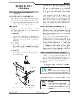
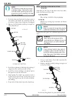
Page 46: ...e cup check the threads before proceeding 6 If used attach the ohmic clip to the shield cup 4T 03 Machine and Hand Torch Parts Selection Depending on the type of operation to be done deter mines the t...

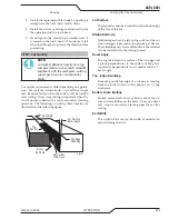
Page 47: ...ty characteristics are illustrated in the following figure Kerf Width Cut Surface Bevel Angle Top Edge Rounding Cut Surface Drag Lines Dross Build Up Top Spatter A 00007 Cut Quality Characteristics Cu...

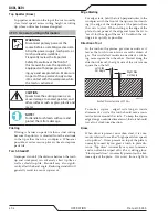
Page 48: ...tly affect the bevel angle Reducing standoff will generally result in a more square cut Edge Starting For edge starts hold the torch perpendicular to the workpiece with the front of the tip near not t...

Page 49: ...t protection Choose the holding technique that feels most comfortable and allows good control and movement NOTE The tip should never come in contact with the workpiece except during drag cutting opera...

Page 50: ...g it onto the torch shield cup Install the guide with the legs at the sides of the shield cup body to main tain good visibility of the cutting arc During operation position the legs of the standoff gu...

Page 51: ...operator s manual NOTE When the shield cup is properly in stalled there is a slight gap between the shield cup and the torch handle Gas vents through this gap as part of normal operation Do not attemp...

Page 52: ...cable connection 4T 07 Gouging WARNING Be sure the operator is equipped with proper gloves clothing eye and ear protection and that all safety precau tions at the front of this manual have been follo...

Page 53: ...andoff Distance The tip to work distance affects gouge quality and depth Standoff distance of 1 8 1 4 inch 3 6 mm allows for smooth consistent metal removal Smaller standoff distances may result in a...

Page 54: ...terial Thickness Gas Pressure Air Arc Voltage Torch Working Height Travel Speed Initial Piercing Height Pierce Delay Kerf Width Rec Speed GA in inch PSI torch lead length Volts in ipm in sec in 20 0 0...

Page 55: ...Rec Speed mm Bar torch lead length Volts mm mm min mm sec mm 1 4 8 7 6m 5 2 15 2m 101 3 6 3990 4 6 0 0 1 1 2 105 3 6 2920 4 6 0 1 1 4 3 109 3 6 1810 4 6 0 3 1 5 4 110 3 6 1470 4 6 0 3 1 6 5 112 3 6 13...

Page 56: ...ge Torch Working Height Travel Speed Initial Piercing Height Pierce Delay Kerf Width Rec Speed GA in inch PSI torch lead length Volts in ipm in sec in 18 0 050 75 25 80 50 110 0 19 60 0 20 0 00 0 07 1...

Page 57: ...orch lead length Volts mm mm min mm sec mm 1 5 2 7 6 5 5 15 2 112 4 8 1670 4 8 0 0 1 7 2 105 4 8 1140 5 1 0 1 1 8 3 109 4 8 980 5 1 0 2 1 8 4 109 4 8 845 5 1 0 3 1 8 5 111 4 8 715 5 1 0 4 1 8 6 118 4...

Page 58: ...sure Air Arc Voltage Torch Working Height Travel Speed Initial Piercing Height Pierce Delay Kerf Width Rec Speed GA in inch PSI torch lead length Volts in ipm in sec in 20 0 040 70 25 75 50 95 0 16 30...

Page 59: ...torch lead length Volts mm mm min mm sec mm 1 0 4 8 7 6m 5 2 15 2m 95 4 1 7620 4 1 0 0 1 5 2 0 104 4 1 3500 4 1 0 2 1 6 3 0 115 4 1 2350 4 6 0 3 1 7 4 0 113 4 6 2170 4 6 0 4 1 7 5 0 118 4 6 1740 4 6...

Page 60: ...l Piercing Height Pierce Delay Kerf Width Rec Speed GA in inch PSI torch lead length Volts in ipm in sec in 16 0 060 85 25 90 50 118 0 19 290 0 19 0 00 0 08 14 0 075 120 0 19 285 0 19 0 10 0 08 11 0 1...

Page 61: ...6m 6 2 15 2m 115 4 8 7540 4 8 0 2 1 2 120 4 8 7015 4 0 0 10 1 9 3 118 4 8 4570 4 8 0 10 0 1 4 120 4 8 3650 4 8 0 20 1 9 5 121 4 8 2465 4 8 0 20 2 1 6 122 4 8 2145 4 8 0 30 2 0 8 123 4 8 1635 4 8 0 40...

Page 62: ...t Travel Speed Initial Piercing Height Pierce Delay Kerf Width Rec Speed GA in inch PSI torch lead length Volts in ipm in sec in 16 0 063 85 25 90 50 119 0 19 350 0 20 0 00 0 05 14 0 078 116 0 19 300...

Page 63: ...ec mm 1 5 9 7 6m 6 2 15 2m 124 4 8 10890 5 1 0 00 0 8 2 116 4 8 7560 5 1 0 10 1 7 3 122 4 8 4365 5 1 0 10 1 7 4 119 4 8 2865 5 1 0 20 2 1 5 122 4 8 2195 5 1 0 20 2 1 6 123 4 8 1790 5 1 0 30 2 2 8 127...

Page 64: ...Working Height Travel Speed Initial Piercing Height Pierce Delay Kerf Width Rec Speed GA in inch PSI torch lead length Volts in ipm in sec in 16 0 064 85 25 90 50 123 0 25 440 0 25 0 00 0 08 14 0 079...

Page 65: ...ec mm 1 5 9 7 6m 6 2 15 2m 118 6 4 17010 6 4 0 00 1 8 2 126 6 4 7680 6 4 0 10 2 3 3 128 6 4 6410 6 4 0 10 2 3 4 130 6 4 5230 6 4 0 20 2 3 5 132 6 4 4010 6 4 0 20 2 4 6 132 6 4 2640 6 4 0 30 2 4 8 137...

Page 66: ...ess Gas Pressure Air Arc Voltage Torch Working Height Travel Speed Initial Piercing Height Pierce Delay Kerf Width Rec Speed GA in inch PSI torch lead length Volts in ipm in sec in 20 0 036 75 25 80 5...

Page 67: ...Rec Speed mm Bar torch lead length Volts mm mm min mm sec mm 1 5 2 7 6 5 5 15 2 108 4 1 3266 4 1 0 0 1 4 2 108 4 1 2239 4 1 0 0 1 5 3 112 4 1 1794 4 1 0 1 1 7 4 114 4 1 1651 4 1 0 2 1 7 5 115 4 1 157...

Page 68: ...Working Height Travel Speed Initial Piercing Height Pierce Delay Kerf Width Rec Speed GA in inch PSI torch lead length Volts in ipm in sec in 18 0 050 75 25 80 50 110 0 16 60 0 16 0 0 0 06 16 0 063 10...

Page 69: ...th Rec Speed mm Bar torch lead length Volts mm mm min mm sec mm 1 5 2 7 6 5 5 15 2 109 4 1 1670 4 1 0 0 1 7 2 114 4 1 1140 4 1 0 1 1 8 3 114 4 1 980 4 1 0 2 1 8 4 116 4 1 845 4 1 0 3 1 8 5 115 4 1 725...

Page 70: ...Voltage Torch Working Height Travel Speed Initial Piercing Height Pierce Delay Kerf Width Rec Speed GA in inch PSI torch lead length Volts in ipm in sec in 20 0 040 75 25 80 50 110 0 19 300 0 20 0 0 0...

Page 71: ...Width Rec Speed mm Bar torch lead length Volts mm mm min mm sec mm 1 0 5 2 7 6 5 5 15 2 110 4 8 7660 5 1 0 0 1 6 2 0 116 4 8 3490 5 1 0 2 1 8 3 0 124 4 8 2350 5 1 0 3 1 8 4 0 126 4 8 2170 5 1 0 4 1 8...

Page 72: ...ight Pierce Delay Kerf Width Rec Speed GA in inch PSI torch lead length Volts in ipm in sec in 16 0 060 85 25 90 50 128 0 19 250 0 20 0 00 0 09 14 0 075 129 0 19 237 0 20 0 10 0 09 11 0 120 126 0 19 2...

Page 73: ...6m 6 2 15 2m 127 4 8 6804 5 1 0 2 2 2 129 4 8 5942 5 1 0 10 2 2 3 126 4 8 5080 5 1 0 10 0 1 4 130 4 8 3316 5 1 0 20 2 3 5 132 4 8 2794 5 1 0 20 2 2 6 134 4 8 2230 5 1 0 30 2 1 8 133 4 8 1425 5 1 0 40...

Page 74: ...d Initial Piercing Height Pierce Delay Kerf Width Rec Speed GA in inch PSI torch lead length Volts in ipm in sec in 16 0 063 85 25 90 50 110 0 13 165 0 20 0 00 0 06 14 0 078 116 0 13 155 0 20 0 10 0 0...

Page 75: ...sec mm 1 5 9 7 6m 6 2 15 2m 101 3 3 4590 5 1 0 00 1 2 2 116 3 3 3925 5 1 0 10 1 7 3 118 3 3 3285 5 1 0 10 1 7 4 126 3 3 1985 5 1 0 20 2 2 5 125 3 3 1850 5 1 0 20 2 1 6 127 3 3 1605 5 1 0 30 2 1 8 131...

Page 76: ...ht Travel Speed Initial Piercing Height Pierce Delay Kerf Width Rec Speed GA in inch PSI torch lead length Volts in ipm in sec in 16 0 064 85 25 90 50 118 0 13 350 0 25 0 00 0 07 14 0 079 118 0 13 350...

Page 77: ...sec mm 1 5 9 7 6m 6 2 15 2m 118 6 4 8890 6 4 0 00 2 2 118 6 4 8890 6 4 0 10 2 0 3 123 6 4 7070 6 4 0 10 2 1 4 124 6 4 5095 6 4 0 20 2 0 5 126 6 4 3335 6 4 0 20 2 0 6 130 6 4 2370 6 4 0 30 2 0 8 134 6...

Page 78: ...at No s 6774336 7145099 6933461 Other Pat s Pending 9 8231 Tip US Pat No s 6774336 7145099 6933461 Other Pat s Pending 9 8211 Tip US Pat No s 6774336 7145099 6933461 Other Pat s Pending 9 8212 Tip US...

Page 79: ...d Cap US Pat No s 6914211 D505309 Other Pat s Pending 9 8245 Shield Cap US Pat No s 6914211 D496951 Other Pat s Pending The following parts are also licensed under U S Patent No 5 120 930 and 5 132 51...

Page 80: ...A40i A60i OPERATION Manual 0 5466 4T 36 This Page Intentionally Blank...

Page 81: ...fore maintaining Each Use Visual check of torch tip and electrode Weekly Visually inspect the torch body consumables and Quick Connect Visually inspect the cables and leads Replace as needed 3 Months...

Page 82: ...kly or Every 30 Cutting Hours 1 Check fan for proper operation and adequate air flow 2 Inspect torch for any cracks or exposed wires replace if necessary 3 Inspect input power cable for damage or expo...

Page 83: ...ble disconnected 5 Worn torch parts 6 Non Genuine Thermal Dynamics parts used Excessive Dross Formation 1 Cutting speed too slow 2 Torch standoff too high from workpiece 3 Worn torch parts 4 Improper...

Page 84: ...ceeded fan failure or other internal fault E002 Input Fault Input voltage outside the range of the unit or internal fault resulting in low bus voltage 1phase 3phase jumpers J300 on Bias PCB set wrong...

Page 85: ...nformation see Section 2 04 Power Supply Specifications on page 2 2 2 Allow unit to cool 3 Return to authorized service center for repair or replacement GAS LED OFF FAULT and MIN pressure indicators f...

Page 86: ...enter for repair or replacement FAULT indicators flashing Error code E012 1 Upper O ring on torch head is in wrong position 2 Torch starter cartridge is stuck 3 Worn or faulty torch parts 4 Shorted To...

Page 87: ...Service Manual A Filter Element Assembly Replacement The Filter ElementAssembly is in the rear panel For better system performance the filter element should be checked per the Maintenance Schedule Se...

Page 88: ...ingle Stage Filter Element Replacement These instructions apply to power supplies where the optional Single Stage Filter has been installed The Power Supply shuts down automatically when the Filter El...

Page 89: ...bed Fitting Spring Assembled Filter O ring Cat No 9 7743 Optional Single Stage Filter Element Replacement 5 Remove the Filter Element from the Housing and set Element aside to dry 6 Wipe inside of hou...

Page 90: ...of the Filter Assembly enough to allow the Filter Elements to move freely 4 Note the location and orientation of the old Filter Elements 5 Slide out the old Filter Elements First Second Stage Cartridg...

Page 91: ...blowing it through with compressed air CAUTION Dry the torch thoroughly before reinstalling O Ring Lubrication An O Ring on the Torch Head and ATC Male Con nector requires lubrication on a scheduled b...

Page 92: ...ay be an O Ring between the shield cup body and drag shield cap Do not lubricate the O Ring Drag Shield Cap Shield Cup Body O Ring No 8 3488 Art A 03878 4 Remove the tip Check for excessive wear indi...

Page 93: ...ization will not be accepted 6 02 Ordering Information Order replacement parts by catalog number and complete description of the part or assembly as listed in the parts list for each type item Also in...

Page 94: ...not shown 9 7742 2 Replacement Filter Element 9 7741 1 Two Stage Filter Kit includes Hose Mounting Screws 9 9387 1 Two Stage Air Filter Assembly 9 7527 1 First Stage Cartridge 9 1021 1 Second Stage C...

Page 95: ...A40i A60i Manual 0 5466 PARTS LIST 6 3 This Page Intentionally Blank...

Page 96: ...3060 7 1 Rack 9 9448 8 1 Mounting Tube 9 9445 9 1 End Cap Assembly 9 7044 10 2 Body Mounting Pinch Block 9 4513 11 1 Pin Mounting Pinch Block 9 4521 12 1 Torch Holder Sleeve 7 2896 13 1 Pinion Assemb...

Page 97: ...A40i A60i Manual 0 5466 PARTS LIST 6 5 Art A 07113 6 1 4 2 3 5 8 10 12 11 7 10 22 19 15 14 16 17 18 20 21 21 13 9 24 23...

Page 98: ...ATC connector 4 7852 1 50 foot 15 2 m Leads Assembly with ATC connector 4 7853 6 Unshielded Mechanized Leads Assemblies with ATC connectors 1 5 foot 1 5 m Le ads Assembly with ATC connector 4 7842 1...

Page 99: ...A40i A60i Manual 0 5466 PARTS LIST 6 7 A 07994_AB 1 4 2 3 5 6 7 8 9 10 12 11 10 13...

Page 100: ...Amps Shield Cup Gouging 9 8241 Shield Cup Body 9 8237 Tips 40 120A GOUGING Shield Cup Body 9 8237 Shield Cup 9 8218 Shield Cap Machine 50 60A 9 8238 Drag Shield Cup 9 8235 Art A 13695 CUTTING STANDOFF...

Page 101: ...h Select SET PURGE mode to confirm the gas operation and purge the torch if needed ACTION Select desired Operating mode RUN LATCH Rapid Auto Restart RAR Gouge Set desired Operating Current Set the Gas...

Page 102: ...lues Third row Conventional load voltage values 4 Sections of the Data Tag may be applied to separate areas of the power supply I Art A 13265_AB Date of Mfr Output Range Amperage Voltage Type of Power...

Page 103: ...d 7 Green Torch Solenoid 5 6 7 8 1 2 3 4 Pilot 1 2 3 4 5 6 7 8 3 Open 2 Orange PIP 1 Black PIP 4 Open 2 PIP Circuit 1 PIP Circuit 3 Not Used 4 Not Used 6 Open Art A 07114 B Hand Torch Pin Out Diagram...

Page 104: ...No s Socket No s 1 2 5 4 3 7 6 8 Main PC Board 1 2 5 4 3 7 6 8 White Black Orange Green Main PC Board Solenoid Torch Leads Torch Head Not Connected Not Connected Main PC Board Main PC Board B Hand Tor...

Page 105: ...CABLE COLOR CODE 3 Red START 4 Black START 5 Yellow DIVIDED ARC V 6 Blue DIVIDED ARC V 10 Brown PLATE CONTACT GND 11 Orange PLATE CONTACT OUT 12 White OK to MOVE CONTACT 13 Red with male faston OHMIC...

Page 106: ...4 ON 30 1 SW3 5 ON 20 1 for ESAB SW3 6 in spare SW3 all OFF 16 7 1 for SC11 Divided arc voltage signal is isolated either the positive signal J1 6 or negative signal J1 5 may be grounded or both can...

Page 107: ...s than 5K ohms However the voltage dropped across the protection PTCs with a 5K load would result in about a 10 measurement error 50K 100K load would be much more practical giving only 1 or less error...

Page 108: ...LE AIR IN 6 G 1 2 0 7 K D300 INPUT BIAS SUPPLY PCB PFC PCB MULTIFUNCTION DISPLAY CONTROL PCB DISPLAY_7SEG_QUAD AC DC FAULT END OF LIFE OVERTEMP MODE KNOB Rotate to Set Current Press to Select Mode KNO...

Page 109: ...ON CABLE FAN1 BASIC CNC OPTIONAL AUTOMATION INTERFACE A SERIES ONLY GND 5V 15V PRI GND PRI 24V 15V 15V GND PRI 50 PIN RIBBON CABLE SIGNALS all others are GND or unused PIN NAME Description means signa...

Page 110: ...A40i A60i APPENDIX Manual 0 5466 A 10 APPENDIX 8 SYSTEM SCHEMATIC 400V 3PHASE CE Art A 13478...

Page 111: ...A40i A60i Manual 0 5466 APPENDIX A 11 Art A 13478...

Page 112: ...A40i A60i APPENDIX Manual 0 5466 A 12 APPENDIX 9 SYSTEM SCHEMATIC 208 480V 3PHASE Art A 13479...

Page 113: ...A40i A60i Manual 0 5466 APPENDIX A 13 Art A 13479...

Page 114: ...Publication History Cover Date Rev Change s Nov 16 2017 AA Manual released Mar 7 2018 AB Remove excess translations of safety section Add a Duty Cycle section 2 update marking table section 4 correct...

Page 115: ...This Page Intentionally Blank...

Page 116: ...840 ASIA PACIFIC Cikarang Indonesia Customer Care Ph 6221 8990 6095 Fax 6221 8990 6096 Rawang Malaysia Customer Care Ph 603 6092 2988 Fax 603 6092 1085 Melbourne Australia Australia Customer Care Ph 1...

Reviews: