A40i, A60i
Manual 0-5466
OPERATION
4-3
12.
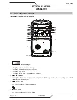
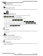
Gas Pressure Indicator
Indicator used to show low, optimal and high gas pressure. Torch type, lead length, cutting mode and amperage should
all be set prior to setting the gas pressure. (90 - 125 PSI / 6.2 - 8.6 bar)
One of 7 segments will always be on when unit is on. The gas bottle will be illuminated and flash during a gas pressure
fault. Bottle will flash when pressure is below a minimum threshold. Bottle will be on continuously when acceptable.
Factory default: One, or two segments and gas bottle will be illuminated depending on the gas pressure level. The
green indicator in the middle indicates the recommended pressure for the process (Amps, torch type, lead length).
Different processes have different optimum pressures.
Yellow indicates above or below optimum pressure and red indicates unacceptable pressure for good cutting. Each
LED represents 5 psi. Two adjacent LEDs will represent a value in between the two or 2.5 lb. pressure change..
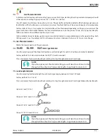
13. Gas Pressure Selector
Rotate the lower knob to set the gas pressure.
14.
Torch Type Indicator
Used for selecting one of the three torch options and torch length for each. SLV will be automatically detected.
Factory default: On, SL60 which includes SL60QD™ (Quick Disconnect)
Press and release the lower knob without rotating it to step through selection of torch type.
NOTE!
If you have gone past the desired setting, you will need to continue to step
through all the other torch types and lengths to get back to return to it..
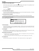
15. Lead Length Indicator
Used for selecting torch lead length for each torch type ranging between 20’ and 100’ leads.
Factory default: On, 20’ or 25'
Press and release the lower knob without rotating it to step through selection of torch type followed by lead length.
Up to 35’ Lead (10.7 m)
Above 35' to 50’ Lead (15.2 m)
Above 50' to 75’ Lead (22.9 m)
Above 75' to 100’ Lead (30.5 m)
NOTE!
If you have gone past the desired setting, you will need to continue to step
through all the other torch types and lengths to get back to return to it..
Summary of Contents for A40i
Page 6: ...This Page Intentionally Blank...
Page 8: ...This Page Intentionally Blank...
Page 12: ...TABLE OF CONTENTS This Page Intentionally Blank...
Page 16: ...A40i A60i WARRANTY INFORMATION Manual 0 5466 W 2 This Page Intentionally Blank...
Page 24: ...A40i A60i INTRODUCTION Manual 0 5466 2T 4 This Page Intentionally Blank...
Page 32: ...A40i A60i INSTALLATION Manual 0 5466 3 8 This Page Intentionally Blank...
Page 34: ...A40i A60i INSTALLATION Manual 0 5466 3T 2 This Page Intentionally Blank...
Page 80: ...A40i A60i OPERATION Manual 0 5466 4T 36 This Page Intentionally Blank...
Page 95: ...A40i A60i Manual 0 5466 PARTS LIST 6 3 This Page Intentionally Blank...
Page 99: ...A40i A60i Manual 0 5466 PARTS LIST 6 7 A 07994_AB 1 4 2 3 5 6 7 8 9 10 12 11 10 13...
Page 110: ...A40i A60i APPENDIX Manual 0 5466 A 10 APPENDIX 8 SYSTEM SCHEMATIC 400V 3PHASE CE Art A 13478...
Page 111: ...A40i A60i Manual 0 5466 APPENDIX A 11 Art A 13478...
Page 112: ...A40i A60i APPENDIX Manual 0 5466 A 12 APPENDIX 9 SYSTEM SCHEMATIC 208 480V 3PHASE Art A 13479...
Page 113: ...A40i A60i Manual 0 5466 APPENDIX A 13 Art A 13479...
Page 115: ...This Page Intentionally Blank...

