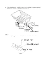
STEP 5
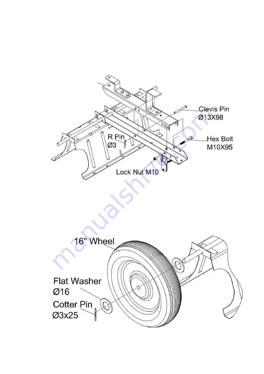
Place draw bar A, inside draw bar B as shown below. Fasten the draw bar sections together using
an M10x95 hex bolt and a M10 lock nut. Tighten, leaving the nut just loose enough that the
sections of the draw bar can pivot freely.
Insert clevis pin Ø13x98 through both parts of the draw bar and secure with an R Pin Ø3.
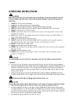
STEP 6
Place Flat Washer Ø16 onto the Axle, followed by the wheel, ensuring the inflation valve is facing
away from the assembly. Add a second Flat Washer Ø16 before inserting Cotter Pin Ø3x25
through the axle.
Repeat the same actions on the opposite side.
Draw Bar A


