background image


23 


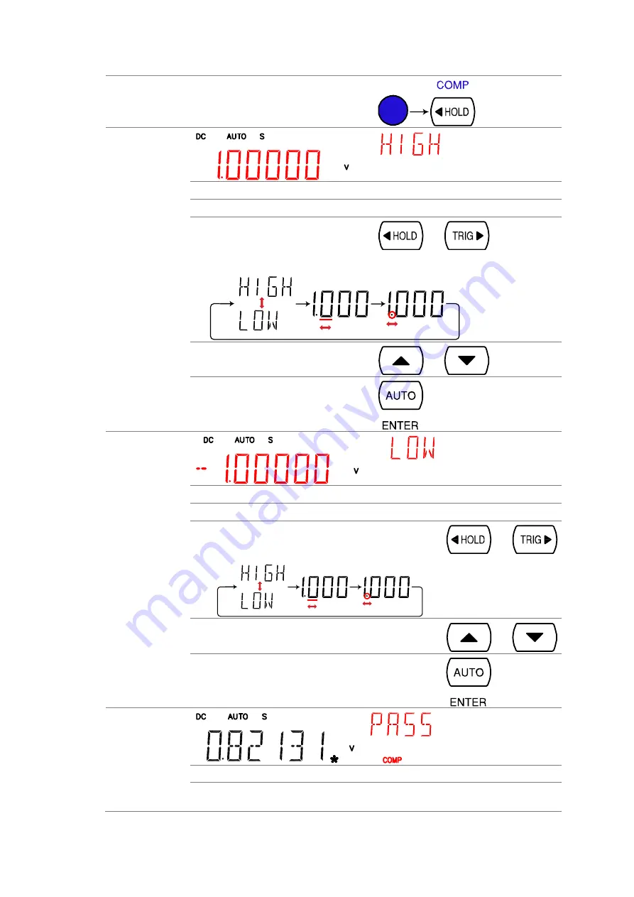
1. Activate 
Compare 
measurement 

Press  the  Shift  key,  then  the  HOLD 
(Comp) key. 


2. High limit 
setting 


1st display 

Shows the high limit value 


2nd display 

Indicates high limit setting 


1.  Use the Left/Right key to move 

the cursor (flashing point) 
between high/low setting, digits, 
and decimal point. 


2. 

Change the parameter using the 
Up/Down key. 


3. 

Press the ENTER key to confirm 
editing and move to the low limit 
setting. 


3. Low limit 
setting 


1st display 

Shows the low limit value 


2nd display 

Indicates low limit setting 


4. 

Use the Left/Right key to move the cursor (flashing 
point) between high/low setting, digits, and decimal 
point. 


5. 

Change the parameter using the Up/Down key. 


6. 

Press the ENTER key to confirm editing. The 
compare measurement starts right away. 


4. Compare 
measurement 
appears 


COMP 

Indicates Compare mode 


2

nd

 display 

Shows the compare measurement result: Pass, High, or 
Low. 

Summary of Contents for DL-2052

Page 1: ...B71 0422 01 INSTRUCTION MANUAL DIGITALMULTIMETER DL 2052 ...

Page 2: ... are the trademark or the registered trademark of each company or group in each country and region About the Instruction Manual Permission from the copyright holder is needed to reprint the contents of this manual in whole or in part Be aware that the product specifications and the contents of this manual are subject to change for the purpose of improvement ...

Page 3: ...ect Resistance range 13 2 13 Diode Test 13 2 14 Continuity Test 13 2 15 Set continuity threshold 14 2 16 Select beeper setting 15 2 17 Frequency Period Measurement 15 2 18 Temperature Measurement 16 2 19 Select thermocouple type 17 2 20 Set reference junction temperature 17 3 ADVANCED MEASUREMENT 19 3 1 Advanced Measurement Overview 19 3 2 Common attribute refresh rate 19 3 3 Common attribute read...

Page 4: ...S 232C interface 38 7 4 Command Syntax 39 7 5 Command Set 40 7 5 1 CONFigure command 40 7 5 2 SENSe command 41 7 5 3 UNIT command 41 7 5 4 CALCulate command 41 7 5 5 TRIGger command 42 7 5 6 SYStem related command 43 7 5 7 STAtus reporting command 43 7 5 8 RS 232C interface command 44 7 5 9 IEEE 488 2 common command 44 7 5 10 Secondary display CONFigure2 command 45 8 APPENDIX 46 8 1 Firmware Versi...

Page 5: ... is incorrectly used in that part a serious danger may be brought about on the user s body or the product To use the part with this pictorial indication be sure to refer to the manuals WARNING If you use the product ignoring this indication you may get killed or seriously injured This indication shows that the warning item to avoid the danger is provided CAUTION If you incorrectly use the product ...

Page 6: ... damage being removed an electric shock or fire may be caused Protective fuse If an input protective fuse is blown the product does not operate For a product with external fuse holder the fuse may be replaced As for how to replace the fuse refer to the corresponding chapter in the instruction manual If no fuse replacement procedures are indicated the user is not permitted to replace it In such cas...

Page 7: ...hipment from the factory they may be deviated more or less by deterioration of parts due to their aging or others It is recommended to periodically calibrate the product so that it is used with its performance and specifications stable For consultation about the product calibration ask us or your local dealer Daily Maintenance When you clean off the dirt of the product covers panels and knobs avoi...

Page 8: ...ite for the latest information and content 1 1 DL 2052 Characteristics The DL 2052 is portable dual display digital multimeters suitable for wide range of applications such as production testing research and field verification Performance High DCV accuracy 0 012 High current range 10A High Voltage range 1000V High ACV frequency response 100kHz Features 119999 meter count Multi functions ACV DCV AC...

Page 9: ...ense LO terminal As a fuse protects the instrument from over current Rating T2A 250V For fuse replacement procedure see page47 As a sense terminal accepts 4W Ω measurement LO connection Also accepts current input less than 2A For details see page12 4W Ω Sense HI Terminal Accepts HI sense line in 4W resistance measurement For details see page12 COM Terminal Accepts ground COM line in all measuremen...

Page 10: ... and goes back to the measurement result display mode ACV Measures AC Voltage page9 DCV Measures DC Voltage page9 ACV DCV When the ACV key and the DCV key are pressed together they measure AC DC Voltage page9 ACI Measures AC Current page11 SHIFT ACI RECALL Recalls a normal measurement result page32 DCI Measures DC Current page11 SHIFT DCI STORE Stores a measurement result page32 ACI DCI When the A...

Page 11: ...urement update rate Slow Medium or Fast page8 Up Down Selects the parameter in various occasions higher or lower HOLD Activates the Hold function page22 SHIFT HOLD COMPare Activates the Compare measurement page22 TRIG Trigger Triggers sample acquisition manually page28 SHIFT TRIG Int Ext Trigger Selects the Internal or the External trigger source page28 Left Right Selects the parameter in various ...

Page 12: ...y page28 Beep page15 Continuity threshold page14 Digital I O page33 and System information 1 5 Rear Panel Overview RS 232 C Port Power Code Socket Fuse T3 15A 250V CAL Key Port Digital I O Port USB Device Port Power Cord Socket Accepts the power cord AC 100 240V 50 60Hz For power on sequence see page7 Fuse Socket Holds the main fuse T3 15A 250V 20VA For fuse replacement details see page46 RS 232C ...

Page 13: ...l I O port Accepts a digital I O cable for the Hi Lo limit test DB 9 pin female connector For digital I O details see page34 1 6 Set Up Tilt stand steps Pull out the handle sideways and rotate it Place the unit horizontally Or in the tilt stand position Place the handle vertically for hand carry ...

Page 14: ... a safety ground This will affect the measurement accuracy 2 Push to turn On the main power switch on the front panel 3 The display shows the model name and the version for a few seconds Example DL 2052 V1 00 4 Followed by the default measurement settings 5 And the interface I O settings 6 Then the default setting appears Example DCV Auto 1V range ...

Page 15: ... data Faster refresh rate yields lower accuracy and resolution Slower refresh rate yields higher accuracy and resolution Consider these trade offs when selecting the refresh rate Range S 5 1 2 digits 119999 count M 4 1 2 digits F 3 1 2 digits Selection step 1 Press the Shift key followed by the AUTO RATE key The refresh rate switches to the next 2 The refresh rate indicator shows the current statu...

Page 16: ... DCV key together 2 ACV DCV mode display appears AC DC V Indicates AC DC AC DC Voltage AUTO Indicates Automatic range selection 100mV 2nd display shows the Voltage range 3 Connect the test lead and measure Connect the test lead between the V and the COM port The display updates the reading V COM Note When measuring in1000V maximum range immediately followed by 100mV minimum range an error might oc...

Page 17: ... 10mV 750 00V 1000V DC AC DC 10mV 1000 0V Note For more detailed parameters see the specifications at page49 2 7 Voltage conversion table This table shows the relationship between AC DC and AC DC reading in various waveforms Waveform Peak to Peak AC True RMS DC AC DC True RMS Sine PK PK 2 828 1 000 0 000 1 000 Rectified Sine full wave PK PK 1 414 0 435 0 900 1 000 Rectified Sine half wave PK PK 2 ...

Page 18: ... waveform as seen from the below table Waveform Shape Crest factor Square wave 1 0 Sine wave 1 414 Triangle sawtooth 1 732 Mixed frequencies 1 414 2 0 SCR output 100 10 1 414 3 0 White noise 3 0 4 0 AC Coupled pulse train 3 0 Spike 9 0 2 9 AC DC AC DC Current Measurement Current type AC 0 10A DC 0 10A AC DC 0 10A AC2 DC2 AC DC AC true RMS 1 Activate ACI DCI Press the ACI AC Current key or the DCI ...

Page 19: ... is not available for AC DC Current For more detailed range see the specifications at page50 2 11 2W 4W Resistance Measurement Measurement type 2 wire Uses the standard V COM ports Recommended for measuring resistances larger than 1kΩ 4 wire Compensates the test lead effect using the 4W compensation ports in addition to the standard V COM ports Recommended for measuring sensitive resistances small...

Page 20: ...0 000MΩ Note For more detailed range see the specifications at page51 2 13 Diode Test Background Diode test checks the forward bias characteristics of a diode by running a constant forward bias current approx 0 5mA through the DUT 1 Activate diode test Press the key once 2 Diode mode display appears V Indicates Diode test DIODE 2nd display shows the title 3 Connect the test lead and measure Connec...

Page 21: ... DUT when testing the continuity Threshold Range 0Ω 1000Ω 1Ω resolution 10Ω default 1 Activate threshold setting 1 Press the Shift key the 2ND key the Right key The measurement menu appears 2 Press the Down key the Right key the Enter key The continuity threshold setting appears 2 Edit threshold 3 Move the cursor the flashing digit using the Left Right key 4 Change the value using the Up Down key ...

Page 22: ...appears 3 Press the Down key The beep setting appears 2 Select the beep setting To change the setting press the Up Down key Beeper type Pass beep when pass Fail beep when fail default Off beep off 3 Go back to the default display Press the Enter key to confirm Press the Exit key to go back to the default display 2 17 Frequency Period Measurement 1 Activate frequency period measurement To measure F...

Page 23: ...rms 2 18 Temperature Measurement Background The DL 2052 accepts thermocouple input and calculates the temperature from the voltage fluctuation Thermocouple type and reference junction temperature are also being considered 1 Activate temperature measurement For Celsius units C press the TEMP key once TEMP For Fahrenheit F unit press the TEMP key twice TEMP TEMP 2 Temperature mode display appears C ...

Page 24: ...e 3 Confirm and go back to the default display Confirm by pressing the Enter key menu of Set reference junction temperature is displayed Press the Exit key to go back to the default display 2 20 Set reference junction temperature Background When a thermocouple is connected to the DL 2052 the temperature difference between the thermocouple lead and the DL 2052 input terminal should be taken into ac...

Page 25: ...ture Use the Left Right key to move the cursor and use the Up Down key to change the value Default 23 00 Press the Enter key to confirm the value or the Exit key to cancel The display goes back to the default state confirm cancel ...

Page 26: ...te yields lower accuracy and resolution Slower refresh rate yields higher accuracy and resolution Consider these trade offs when selecting the refresh rate Range S 5 1 2 digits 119999 count M 4 1 2 digits F 3 1 2 digits Selection step 1 Press the Shift key followed by the AUTO RATE key The refresh rate switches to the next 2 The refresh rate indicator shows the current status 3 3 Common attribute ...

Page 27: ...m Press the Shift key followed by the key The 1st display shows dBm and the 2nd display shows the reference resistance dBm result appears dBm Indicates dBm measurement 600Ω 2nd display indicates the reference resistance Select reference resistance To change the reference resistance press the Up Down key The new resistance appears in the 2nd display The following is the resistance list 2 4 8 16 50 ...

Page 28: ...y shows the Min Max measurement result Deactivate Max Min measurement To cancel the Max Min measurement press the MX MN key for 2 seconds or simply activate another measurement 3 9 Relative Value Measurement Applicable to DCV ACI DCI 2 4W ACV Hz P TE MP Background Relative measurement stores a value typically the data at the moment as the reference The following measurement is shown as the delta b...

Page 29: ...he reading fluctuates more than the threshold setting as the percentage of the retained data 1 Activate Hold measurement Press the HOLD key 2 Hold measurement display appears HOLD Indicates Hold measurement 2nd display Shows the Hold threshold 1st display The measurement data which is updated only when it fluctuates more than the threshold compared to the retained value 3 Select hold threshold Sel...

Page 30: ...3 Press the ENTER key to confirm editing and move to the low limit setting 3 Low limit setting 1st display Shows the low limit value 2nd display Indicates low limit setting 4 Use the Left Right key to move the cursor flashing point between high low setting digits and decimal point 5 Change the parameter using the Up Down key 6 Press the ENTER key to confirm editing The compare measurement starts r...

Page 31: ...pare measurement To cancel the Compare measurement press the Shift key followed by the HOLD Comp key or simply activate another measurement 3 12 Math Measurement Applicable to DCV ACI DCI 2 4W ACV Hz P TE MP Background Math measurement runs three types of mathematical operation MX B 1 X and percentage based on the other measurement results Math type MX B Multiplies the reading X by the factor M an...

Page 32: ...dicates MX B The letter B flashes 4 Use the Left Right key to move the cursor flashing point between the offset digits and decimal point 5 Change the parameter using the Up Down key 6 Press the ENTER key to confirm the editing The MX B measurement result appears 4 View MX B 1st display Shows the calculated result 2nd display Indicates MX B MATH Indicates Math operation 3 14 Measure 1 X 1 Activate ...

Page 33: ...tage is calculated as Reading Reference Reference x 100 2 Set the reference number 1st display Shows the reference number 2nd display Indicates Percentage setting 1 Use the Left Right key to move the cursor flashing point between high low setting digits and decimal point 2 Change the parameter using the Up Down key 3 Press the ENTER key to confirm editing 3 View Percentage 1st display Shows the ca...

Page 34: ...ce needs to be larger than 1MΩ Some combination of dual display mode is possible but may not be useful and their accuracies are not guaranteed 2 nd Measurement item setting Press the 2nd key then the target item example ACV The display updates the measurement result example ACI ACV 1 st Display Shows the primary measurement result 2 nd Display Shows the secondary measurement result 2ND Indicates t...

Page 35: ...r Setting 4 2 1 Manual Automatic triggering Automatic triggering default The DL 2052 triggers according to the refresh rate See the previous page for refresh rate setting details Manual triggering Press the TRIG key to trigger measurement manually 4 2 2 Use external trigger Background The DL 2052 uses the internal trigger by default for example to count the frequency and the period Using an extern...

Page 36: ...key followed by the TRIG key The EXT indicator disappears and the trigger goes back to internal mode 4 2 3 Set trigger delay Background Trigger delay defines the time rag between triggering and measurement start The default is set at 10ms Panel operation 1 Press the Shift key the 2ND Menu key the Right key the Down key The delay menu appears 2 Press the Down key The delay setting appears 3 Move th...

Page 37: ...nd is recommended for most applications 1 Sample 1st reading Sample 1 4 2nd reading Sample 2 5 3 2 4 5 6 7 8 9 10 11 12 3rd reading Sample 3 6 Repeating REP Repeating filter renews the whole samples per reading 1 Sample 1st reading Sample 1 4 2nd reading Sample 5 8 3 2 4 5 6 7 8 9 10 11 12 3rd reading Sample 9 12 Filter count Filter count defines the number of samples to be averaged per reading Mo...

Page 38: ...ess the Down key then the Right key twice The light menu appears 3 Press the Down key The light level setting appears 1st display Shows the current display light level 4 Select the level using the Up Down key 5 Press the Enter key to confirm your selection Press the Exit key to go back to the default display 4 4 2 Display on off setting key lock Background The display can be turned off when not us...

Page 39: ... key Change the data count using the Up Down key 3 Press the Enter key to confirm editing and to go back to the previous display STO Indicates the measurement history is stored 5 2 Recall Measurement Record Background The DL 2052 can recall the stored measurement history for observation and analysis as in Maximum Minimum and Average value Not applicable to Store recall measurement history is not a...

Page 40: ...splay 5 4 Recall Settings Background The DL 2052 can be called the initial configuration and 10 different panel settings Also when a call set up once same set is called the next time the power is turned on It becomes the factory settings when you call the 00 Parameter 00 10 Recall stored Settings 1 Press the Shift key followed by the 2nd MENU key The SYSTEM menu appears 2 Move the cursor using the...

Page 41: ...ection Pin3 Digital Chassis Ground Pin4 External Trigger Input Accepts external trigger signal For using external signals Pin5 PASS signal Output Activates when the compare result is PASS Active low Pin6 FAIL signal Output Activates when the compare result is FAIL Active low Pin7 HIGH Limit FAIL signal Output Activates when the compare result is FAIL due to violating the HIGH Limit Active low Pin8...

Page 42: ...nt 2 Change the parameter using the Up Down key 3 Press the ENTER key to confirm editing and move to the low limit setting 3 Low limit setting 1st display Shows the low limit value 2nd display Indicates low limit setting Set the low limit in the same way as in the high limit Press the ENTER key to confirm editing The compare measurement starts right away 4 Compare measurement appears COMP Indicate...

Page 43: ...Connect the external trigger signal to the Digital I O port located on the rear panel 1 2 3 4 5 6 7 8 9 FAIL Out HIGH Limit FAIL Out LOW Limit FAIL Out EOM Out VCC Out NC Digital Chassis Ground External Trigger In PASS Out Pin4 External Trigger Input pin TTL level Active High Pulse width 25us 1 Activate external trigger Press the Shift key followed by the TRIG key The EXT indicator appears on the ...

Page 44: ...t key the 2ND Menu key the Right key twice The I O configuration menu appears 2 Press the Down key The USB selection display appears 3 Press the Down key The USB ON OFF selection appears 4 Press the Up Down key to select ON or OFF 5 Press the ENTER key to confirm USB selection NOTE If USB is ON RS 232C is disable 6 Press the Exit key to go back to the default display NOTE Can t communicate when me...

Page 45: ...00 57600 38400 19200 9600 4 Press the ENTER key to confirm RS 232C and baud rate selection 5 Press the Exit key to go back to the default display Can t communicate when menu is displayed 6 Connect the RS 232C cable to the rear panel terminal RS 232C pin assignment Pin 2 RxD Pin 3 TxD Pin 5 GND Pin 1 4 6 9 No Connection 5 4 3 2 1 9 8 7 6 PC Connection Null modem connection in which transmit TxD and...

Page 46: ... selection The DL 2052 automatically translates the command parameter into the closest available value Example 1 conf volt dc_1 Sets the measurement item to DC Voltage and the range to 1V the DL 2052 selects the 1V range Example 2 conf volt dc_2 Sets the measurement item to DC Voltage and the range to 2V There is no 2V range so the DL 2052 selects the closest range 10V Query example READ Respond m...

Page 47: ...and specifies range Parameter NR2 min max Example conf curr dcac_10 DC ACI 10A range Example conf curr dcac_min DC ACI minimum range conf res Sets measurement to 2W Resistance and specifies range Parameter NR2 min max Example conf res_10e3 2W R 10K range Example conf res_min 2W R minimum range conf fres Sets measurement to 4W Resistance and specifies range Parameter NR2 min max Example conf fres_1...

Page 48: ...count 100 sens aver coun Returns current digital filter count Parameter 2 100 sens aver stat Turns digital filter On Off Parameter Boolean Example sens aver stat_1 digital filter On sens aver stat Returns digital filter status On or Off Parameter Boolean 7 5 3 UNIT command unit temp Selects temperature unit celsius or fahrenheit Parameter c celsius f fahrenheit Example unit temp_c temperature unit...

Page 49: ... min max Example calc lim low_1 0 lower limit set to 1 0 calc lim low Returns lower limit value in Compare measurement Parameter NR2 min max calc lim upp Sets upper limit value in Compare measurement Parameter NR2 min max Example calc lim low_1 0 upper limit set to 1 0 calc lim upp Returns upper limit value in Compare measurement Parameter NR2 min max calc math mmf Sets factor M in Math measuremen...

Page 50: ... trigger counting Parameter NR1 1 to 127 Example trig coun_100 trigger count set at 100 trig coun Returns number of trigger count Parameter NR1 1 to 127 trac data Returns buffer contents trac cle Clears buffer contents 7 5 6 SYStem related command syst disp Turns display On or Off Parameter Boolean Example disp_1 display On syst disp Returns display status On of Off Parameter Boolean syst beep sta...

Page 51: ...tents Example ese 65 sets ESER to 01000001 esr Returns and clears SESR Standard Event Status Register Example 198 means SESR 11000110 value Bit EVENT 128 32 16 8 4 1 7 5 4 3 2 0 POWER ON Command Error Execute Error Device Error Query Error Execute Complete idn Returns company name model No and system version Example TEXIO DL 2052 1 0 opc 1 is placed in the output queue when all the pending operati...

Page 52: ...2 fres Configure 2 nd display to 4W Resistance Parameter NR2 min max Example conf2 fres_10e2 Resistance 1kΩ range conf2 freq Configure 2 nd display to Frequency conf2 per Configure 2 nd display to Period conf2 temp Configure 2 nd display to Temperature conf2 off Turn off the dual display mode 2 nd display is off conf2 stat func Returns function of 2 nd display Parameter 1 DCV 2 ACV 3 DCA 10A 4 ACA...

Page 53: ...wed by the 2ND Menu key The system menu appears 8 Press the Down key followed by the Right key The firmware version menu appears 9 Press the Down key The firmware version appears 10 Press the Exit key to go back to the default display 8 2 Fuse Replacement 8 2 1 Replace AC source fuse Step 11 Take off the power cord and remove the fuse socket using a minus driver 12 Replace the fuse in the holder R...

Page 54: ...47 8 2 2 Replace input current fuse Step 13 Press the Fuse holder 14 The fuse holder comes out Replace the fuse inserted at the end of the holder Rating T2A 250V ...

Page 55: ...48 8 3 Status system ...

Page 56: ...60Hz Dimension 265 W x 107 H x 350 D mm Weight Approx 2 6kg without option 9 2 Reading rates readings sec Function Rate S M F DCV 10 30 60 DCI 10 30 60 ACV 1 5 20 ACI 1 5 20 2 4WΩ 10M 100MΩ 1 1 5 2 2 4WΩ others 3 5 8 ACV DCV 0 5 1 3 ACI DCI 0 5 1 3 Diode 30 30 60 9 3 DC Voltage Note Max Input 1000V DC or Peak on all range Rate Range Resolution Full Scale Accuracy Input Impedance S 100 000mV 1µV 12...

Page 57: ...uracy reading digits 20 45Hz 45 10kHz 10k 30kHz S 100 000mV 1 100 0 2 100 1 5 300 1 00000V 1 100 0 2 100 1 100 10 0000V 1 100 0 2 100 1 100 100 000V 1 100 0 2 100 1 100 750 00V 1 100 0 2 100 1 100 M 100 00mV 0 2 40 1 5 80 1 0000V 0 2 40 1 40 10 000V 0 2 40 1 40 100 00V 0 2 40 1 40 750 0V 0 2 40 1 40 F 100 0mV 0 2 5 1 5 10 1 000V 0 2 5 1 5 10 00V 0 2 5 1 5 100 0V 0 2 5 1 5 750V 0 2 5 1 5 9 5 DC Cur...

Page 58: ... 10mA 1 20A 10 00A 10mA 10 00A Accuracy reading digits Rate Range 20 50Hz 50 10kHz S 10 0000mA 1 5 100 0 5 100 100 000mA 1 5 100 0 5 100 1 0000A 1 100 10 0000A 1 100 M 10 000mA 0 5 40 100 00mA 0 5 12 1 000A 10 000A F 10 00mA 0 5 5 100 0mA 0 5 2 1 00A 10 00A 9 7 2W Resistance Note Max Input 500V DC or 500V rms AC Relative mode Rate Range Full Scale Accuracy reading digits S 100 000Ω 120 000Ω 0 1 8 ...

Page 59: ... 2 1 000kΩ 1 200kΩ 0 05 2 10 00kΩ 12 00kΩ 0 05 2 100 0kΩ 120 0kΩ 0 05 2 1 000MΩ 1 200MΩ 0 05 2 10 00MΩ 12 00MΩ 1 5 2 100 0MΩ 120 0MΩ 5 0 2 9 9 Diode Continuity Note Max Input 500V DC or 500V rms AC Item Range Diode Approx 2V 0 5mA Continuity 1 1000Ω 9 10 Frequency Note Max Input 750V rms or 1000V peak Frequency Sensitivity Accuracy reading digits 10Hz 100kHz 0 1V 0 05 15 100kHz 600kHz 1V 0 05 3 60...

Page 60: ...53 9 13 External Dimensions Figure ...

Page 61: ...7F Towa Fudosan Shin Yokohama Bldg 2 18 13 Shin Yokohama Kohoku ku Yokohama Kanagawa 222 0033 Japan http www texio co jp ...

Reviews: