Board Layout
www.ti.com
3
Board Layout
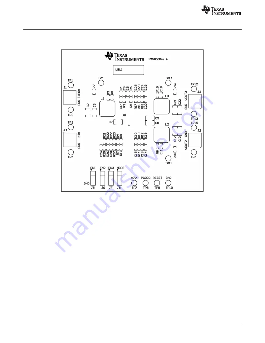
Figure 2
illustrates the PCB layout for this EVM.
Figure 2. Component Placement (Top Layer)
4
TPS65261EVM-650 PMIC 3-A, 2-A, 2-A Output Current Evaluation Module
SLVUA85 – June 2014
Submit Documentation Feedback
Copyright © 2014, Texas Instruments Incorporated


