www.ti.com
2.3
Functional Operation
2.3.1
One-Shot Mode Operation
Write
PWM START
PWM START
Write
P1D
PER+1
PWM output
Interrupt
2.3.1.1
Event-Triggered One-Shot Mode Operation
Peripheral Architecture
The PWM module can operate in either one-shot or continuous mode. In both modes, the PWM peripheral
has a first-phase duration register (PH1D) and a period register (PER) to specify, respectively, the
first-phase duration and period of the waveform. The first-phase output level can be configured to be
either high or low in the P1OUT bit of the PWM configuration register (CFG) and the second phase output
is automatically the opposite polarity of the first-phase level. The inactive state before and after the PWM
operation can also be configured to be either a 0 or a 1 in the INACTOUT bit of CFG. For one-shot mode
operation, see
; for continuous mode operation, see
In one-shot mode operation, the PWM produces a series of periods but does not run continuously. The
number of periods in the series is controlled by the repeat count contained in the PWM repeat count
register (RPT). To select one-shot mode, configure the MODE bit in the PWM configuration register (CFG)
to 1h.
For one-shot mode operation, the PWM should first be configured for mode, period, and first-phase
duration, along with other configuration options. The PWM uses the last programmed set of parameters
once it is started by writing a 1 to the START bit in the PWM start register (START).
Once started, the PWM asserts/deasserts the output as configured, driving to the first-phase output level
during the first phase and the opposite level during the second phase. When the prescribed number of
RPT + 1 periods of pulses expire, the peripheral sends an interrupt to the system (if the interrupt is
enabled in CFG). The PWM then becomes inactive until the START bit is written a 1 again.
The PWM is stopped during one-shot mode operation by changing the MODE bit to 0 (disable). When the
PWM is disabled, the output is immediately driven to the configured inactive state.
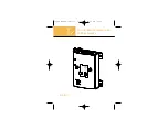
shows the one-shot mode operation. The waveform generation is started by writing to the START
bit (assuming event triggering is disabled). After RPT + 1 number of periods, the waveform stops and an
interrupt is generated. The polarity is configured as inactive low, first phase high-then-low.
Figure 2. PWM One-Shot Mode Operation (P1OUT = 1, INACTOUT = 0, EVTRIG = 0, PWM_RPT = 2)
In one-shot mode, the PWM senses a rising or falling transition on an event-trigger input signal to start the
operation. This event trigger input is synchronized to the PWM clock inside the module and is driven by
the video processing subsystem CCDC_VD output signal. This capability is provided to allow the PWM to
be used as a CCD timer.
The trigger event can be detected on the rising edge or the falling edge of CCDC_VD. After event
triggering is enabled as part of the configuration process, a write to the PWM START register (START)
starts the sensing circuitry in the PWM and after the first event, the PWM starts the period counting.
shows the event-triggered one-shot mode operation. Note that each subsequent event does not
restart period counting. It takes another write to the START bit to sense the event signal again. Also note,
that events received within the PWM period are ignored as well.
10
Pulse-Width Modulator (PWM) Peripheral
SPRUEE7A – May 2006 – Revised September 2007