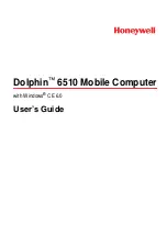
CLK
CLKC
ADC[15:0]P
ADC[15:0]N
t
h(ADC[#]P)
1/f
CLK(ADC)
t
su(ADC[#]P)
T0291-01
CLK
CLKC
ADC[# bits/2]P
ADC[# bits/2]N
Odd Bits
Odd Bits
t
su(ADCx[#/2]P)
T0293-01
1/f
CLK(ADCx)
Even Bits
Even Bits
t = N + 1
t = N
t
h(ADCx[#/2]P)
GC5328
www.ti.com
SLWS218A – OCTOBER 2009 – REVISED OCTOBER 2009
LVDS SWITCHING CHARACTERISTICS
over recommended operating conditions (unless otherwise noted). The following table uses a shorthand nomenclature, NxM.
N means the number of differential pairs used to transmit data from one ADC, and M means the number of bits sent serially
down each LVDS pair. Thus, 8x2 means eight LVDS pairs, each containing 2 bits of information sent serially. NOTE: The
ADC clock rate must match the DPDClock rate for real feedback.
PARAMETER
TEST CONDITIONS
MIN
TYP
MAX
UNIT
16x1 SDR LVDS MODE ex. ADS5444
f
CLK(ADC)
ADC interface clock frequency
See
(1)
200
MHz
t
su(ADC[#]P)
Input data setup time before CLK
↑
See
(1) (2)
300
ps
t
h(ADC[#]P)
Input data hold time after CLK
↑
See
(1) (2)
600
ps
8x2 DDR LVDS MODE ex. ADS5545, ADS6149
f
CLK(ADCA)
ADCA interface clock frequency
See
(1)
200
MHz
t
su(ADCA[#/2]P)
Input data setup time before CLK
↑↓
See
(1) (3)
. For port A
430
ps
t
h(ADCA[#/2]P)
Input data hold time after CLK
↑↓
See
(1) (3)
. For port A
260
ps
f
CLK(ADCB)
ADCB interface clock frequency
See
(1)
200
MHz
t
su(ADCB[#/2]P)
Input data setup time before CLK
↑↓
See
(1) (4)
. For port B
800
ps
t
h(ADCB[#/2]P)
Input data hold time after CLK
↑↓
See
(1) (4)
. For port B
400
ps
(1)
Specifications are limited by GC5328 performance and may exceed the example ADC capabilities for the given interface.
(2)
Setup and hold measured for ADC[15:0]P, ADC[15:0]N valid for (VOD > 250 mV) to/from ADCCLK and ADCCLKC clock crossing
(VOD = 0).
(3)
Setup and hold measured for ADCA[7:0]P, ADCA[7:0]N valid for (VOD > 250 mV) to/from ADCACLK and ADCACLKC clock crossing
(VOD = 0).
(4)
Setup and hold measured for ADCB[7:0]P, ADCB[7:0]N valid for (VOD > 250 mV) to/from ADCBCLK and ADCBCLKC clock crossing
(VOD = 0).
Figure 18. LVDS Timing Specification (16x1 SDR LVDS)
Figure 19. LVDS Timing Specification (8x2 DDR LVDS)
Copyright © 2009, Texas Instruments Incorporated
Submit Documentation Feedback
23
Product Folder Link(s):
GC5328
Summary of Contents for GC5328
Page 26: ......