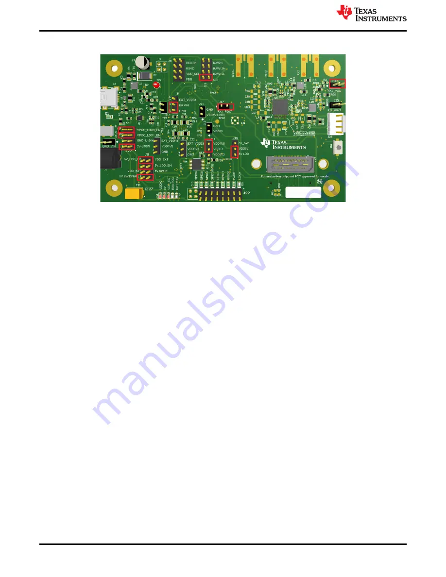
2. Ensure jumpers and switches for DS90UB954-Q1EVM (or variant) are configured like shown in
(SNLU223) for further details.
Figure 2-4. DS90UB954-Q1EVM (or variant) With Jumpers Highlighted
3. Connect the DACAR coax cable with FAKRA connector to RX0p from the DS90UB954-Q1EVM (or variant)
to J16 of the DS90UB95x-Q1EVM
4. Connect a mini USB to J2 on the DS90UB954-Q1EVM (or variant) and J9 on the DS90UB95x-Q1EVM to a
device with Analog LaunchPAD (ALP) software installed
5. Power the DS90UB954-Q1EVM (or variant) with 12 V through J1
6. Open ALP and assign the correct DS90UB953 and DS90UB954 (or variant) profiles to the appropriate USB
IDs
7. The DS90UB95x-Q1EVM and DS90UB954-Q1EVM (or variant) should now be linked and have established
connection. Go to information tab on the DS90UB954 (or variant) device window and confirm that Pass Sts
displays Pass and Linked has the appropriate frequency displayed. Also check if Pass and Lock LEDs are lit
8. Navigate back to the Scripting tab of the DS90UB954 (or variant) ALP profile and run the
953to954_patgen_YUV_1920x1080p-4Lanes-Working.py script to initialize a pattern generation test from
the 953. The script may be found by clicking on the "Run PreDef Script" button. If the DS90UB954-Q1 (or
variant) is not using an I2C address of 0x7A (8-bit form), the script should be modified to use the correct I2C
address. Go back to the information tab of the DS90UB954-Q1 (or variant) and confirm the horizontal and
vertical parameters read 3820 bytes and 1080 lines, respectively.
9. If there are any problems, consult
for an in-depth step-by-step guide to enable the pass and lock
2.5 Use With DS90UB935-Q1
The only modification required to use the DS90UB95x-Q1EVM to evaluate the DS90UB935-Q1 is to exchange
the DS90UB953-Q1 with the DS90UB935-Q1. No additional rework is required.
Quick Start Guide
6
DS90UB95x-Q1 Serializer Evaluation Module
SNLU224C – SEPTEMBER 2017 – REVISED APRIL 2021
Copyright © 2021 Texas Instruments Incorporated


