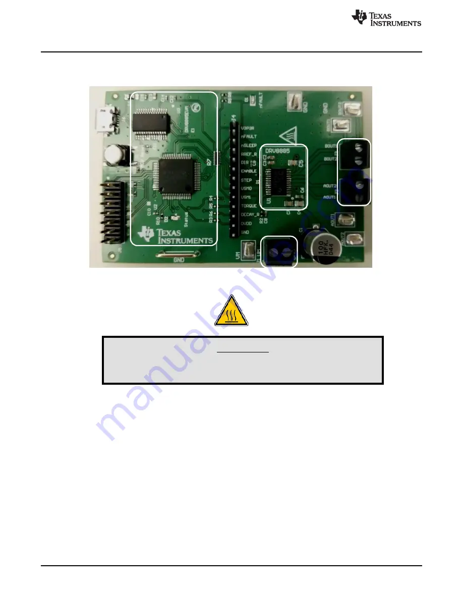
background image

DRV8886AT

Motor

Connections

Power Connector

Microcontroller

Section

Micro

USB

Header

Board Overview

www.ti.com

2

SLVUB16 – February 2017

Submit Documentation Feedback

Copyright © 2017, Texas Instruments Incorporated

DRV8886AT Evaluation Module User's Guide

1

Board Overview

shows the top view of the printed circuit board (PCB).

Figure 1. Top View of Typical Board Configuration (EVM Provided May Vary)

WARNING

The DRV8886AT (U1) can operate at temperatures approaching
150ºC. This device should not be touched.

2

Introduction

The DRV8886AT customer EVM is a platform revolving around the DRV8886AT, a medium-voltage dual
H-bridge driver and highly-configurable power stage. This device has been optimized to drive a single
bipolar stepper with up to 16 degrees of internally generated microstepping.

The EVM houses an MSP430™ microcontroller and an USB interface chip. The USB chip allows for serial
communications from a PC computer where a Windows

®

application is used to schedule serial

commands. These commands can be used to control each of the device signals, and drive the stepper
motor by issuing the step commands at the desired rate.

The microcontroller firmware operates using an internal index mode.

This user's guide details the operation of the EVM, as well as the hardware configurability of the
evaluation module.

2.1

Connectors

The DRV8886AT EVM offers access to the VM (motor voltage) power rail through a terminal block (J1). A
set of test clips in parallel with the terminal block allows for the monitoring of the input power rail.

The user must apply the VM voltage according to recommended parameters listed in the data sheet.

Summary of Contents for DRV8886AT

Page 1: ...and Move Steps 7 2 7 EVM documentation 9 Appendix A Driver and GUI Installation Instructions 10 List of Figures 1 Top View of Typical Board Configuration EVM Provided May Vary 2 2 Connections DRV8885...

Page 2: ...ipolar stepper with up to 16 degrees of internally generated microstepping The EVM houses an MSP430 microcontroller and an USB interface chip The USB chip allows for serial communications from a PC co...

Page 3: ...d To disconnect the internal MSP430 microcontroller remove the R3 R4 R5 and R6 resistors and resistor pack R7 Table 1 describes the connections available on the J4 header Each header pin is labeled on...

Page 4: ...and the EVM When the USB is connected to the EVM the status LED will begin to blink Step 5 Open the GUI The GUI can be found in the start menu at Texas Instruments DRV8886_EVM DRV8886_EVM X Y Z where...

Page 5: ...s the nSLEEP pin is used to wake the DRV8886AT The ENABLE toggle button which controls the ENABLE pin is used to enable the DRV8886AT outputs A message stating Both WAKE and ENABLE must be green to en...

Page 6: ...steps in the direction initially set by the control inputs After a short pause the motor then advances the same number of steps in the opposite direction This sequence is repeated until the Reciprocat...

Page 7: ...troller transforms it into the respective clock cycles required for the timer to generate accurate STEP pulse timing 2 6 1 Start Stop Steps The acceleration profile is coded inside of the microcontrol...

Page 8: ...Number of Steps This parameter is the number of steps that the controller will issue Steps to Stop The controller is continuously monitoring the step being issued and when the current step is equal t...

Page 9: ...9 SLVUB16 February 2017 Submit Documentation Feedback Copyright 2017 Texas Instruments Incorporated DRV8886AT Evaluation Module User s Guide Figure 8 Stop Conditions 2 7 EVM documentation The EVM sche...

Page 10: ...perties go to the Compatibility tab check the Run this program in compatibility mode for option select the Windows XP Service Pack 2 option and click the OK button Next run the CDM v2 10 00 WHQL Certi...

Page 11: ...opyright 2017 Texas Instruments Incorporated Driver and GUI Installation Instructions Click the Next button to continue see Figure 10 Figure 10 EVM Setup Wizard Click the I accept the agreement radio...

Page 12: ...UI Installation Instructions Click the Next button to continue see Figure 12 Figure 12 Installation Folders At this point a few options may appear If the GUI Composer Runtime has not been previously i...

Page 13: ...and GUI Installation Instructions If the GUI has been previously installed a message similar to the one in Figure 14 appears If this message appears click the Yes button and then click the Next button...

Page 14: ...mit Documentation Feedback Copyright 2017 Texas Instruments Incorporated Driver and GUI Installation Instructions Click the check box next to the desired results and then click the Finish button to co...

Page 15: ...set forth above or credit User s account for such EVM TI s liability under this warranty shall be limited to EVMs that are returned during the warranty period to the address designated by TI and that...

Page 16: ...the antenna types listed in the user guide with the maximum permissible gain and required antenna impedance for each antenna type indicated Antenna types not included in this list having a gain great...

Page 17: ...t the EVM user guide prior to connecting any load to the EVM output If there is uncertainty as to the load specification please contact a TI field representative During normal operation even with the...

Page 18: ...OST OF REMOVAL OR REINSTALLATION ANCILLARY COSTS TO THE PROCUREMENT OF SUBSTITUTE GOODS OR SERVICES RETESTING OUTSIDE COMPUTER TIME LABOR COSTS LOSS OF GOODWILL LOSS OF PROFITS LOSS OF SAVINGS LOSS OF...

Page 19: ...TI Resource NO OTHER LICENSE EXPRESS OR IMPLIED BY ESTOPPEL OR OTHERWISE TO ANY OTHER TI INTELLECTUAL PROPERTY RIGHT AND NO LICENSE TO ANY TECHNOLOGY OR INTELLECTUAL PROPERTY RIGHT OF TI OR ANY THIRD...

Reviews: