200
200
200
200
200
Power
supply
R
LOAD
+ -
200
200
200
200
200
Modify components
Additional Evaluation Setups
7
SLVUAN2A – May 2016 – Revised July 2016
Copyright © 2016, Texas Instruments Incorporated
bq77905 3-5S Low Power Protector Evaluation Module
3.4
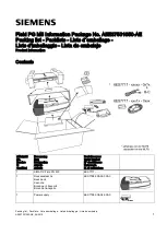
Stacking Modules
While the bq77905 EVM modules do not stack as delivered, they can be modified for a basic
demonstration of stacking by adding additional components. The resulting circuit is not ideal because the
ESD capacitors will remain across each module rather than across the pack terminals. The charge and
discharge FETs installed are 60-V rated and will normally accommodate connection of two EVMs.
Connection of more than two EVMs is not supported by the patterns on the board and is not
recommended. Before connecting the modules, the bottom module must have component additions and
changes shown in
to enable the stacking inputs and support the UV load removal recovery
detection for the upper device. A connection example of the two modules is shown in
.
Table 2. Bottom Module Modifications for Stacking
Reference Designator
Action
Function
R2
Install 10-M
Ω
resistor
Stacking interface
R3
Install 10-M
Ω
resistor
R6
Remove
R7
Remove
R20
Install 470-k
Ω
resistor
UV Load Detect Recovery
D3
Install BAS16J switching diode
Figure 5. Stacking Circuit Modules